Comprehensive control box of towel rapier loom

A rapier loom and comprehensive control technology, which is applied in the field of control boxes, can solve the problems of affecting the heat dissipation effect of the control box and the blockage of the filter mesh.

Inactive Publication Date: 2021-08-24
绍兴市嘉纬电子科技有限公司
View PDF1 Cites 2 Cited by
  • Summary
  • Abstract
  • Description
  • Claims
  • Application Information

AI Technical Summary

Problems solved by technology

[0004] However, when the filter screen is used to filter the dust in the air, the dust will adhere to the filter screen. When the control box is not in use, the outside air will still pass through the filter screen. When the control box is not in operation, the filter screen will still filter the air. There is more and more dust attached to the filter, which may cause the mesh holes on the filter to be blocked and affect the heat dissipation effect of the control box.

Method used


Image

  • Comprehensive control box of towel rapier loom
  • Comprehensive control box of towel rapier loom
  • Comprehensive control box of towel rapier loom

Examples


Embodiment 1

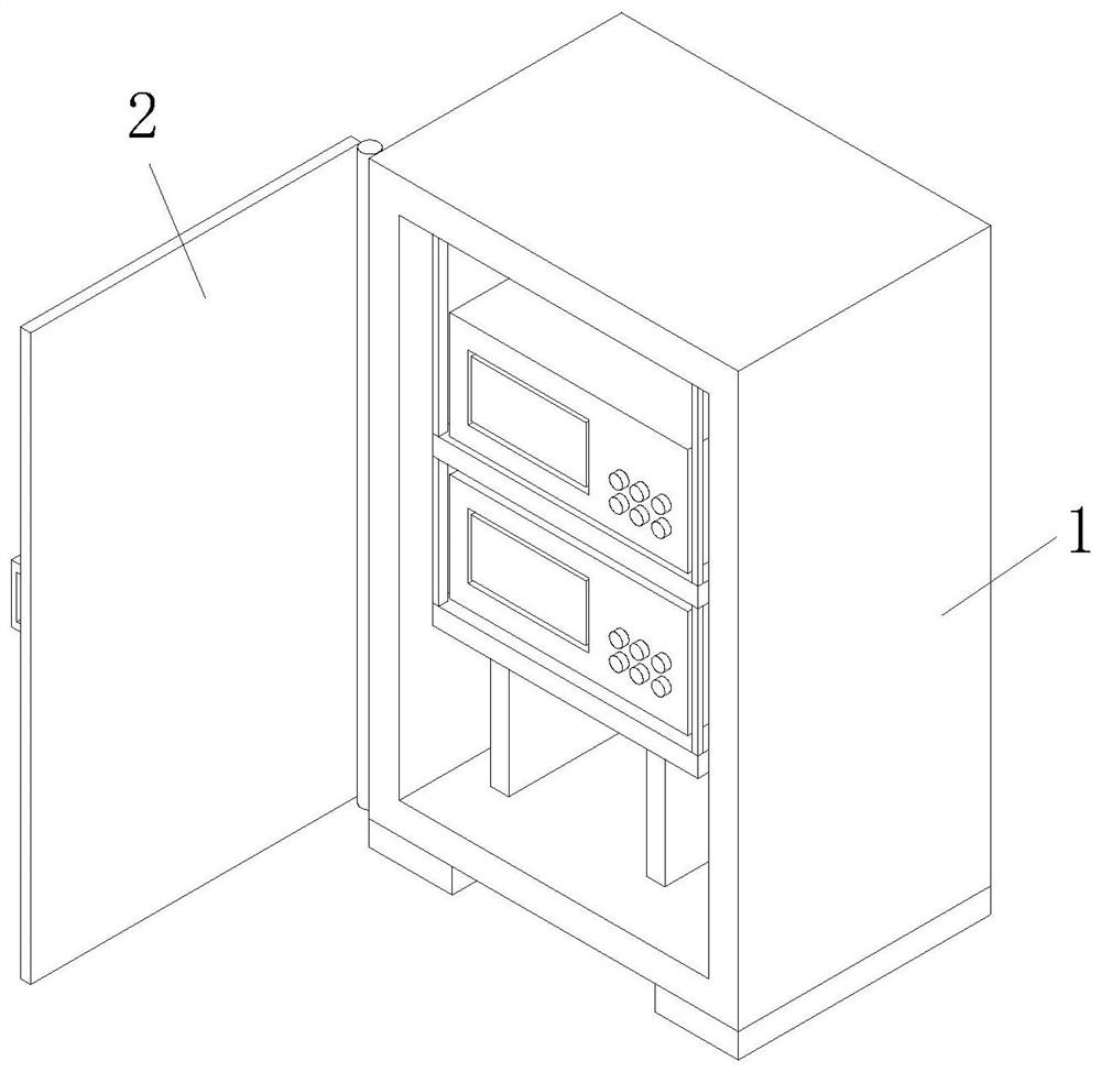
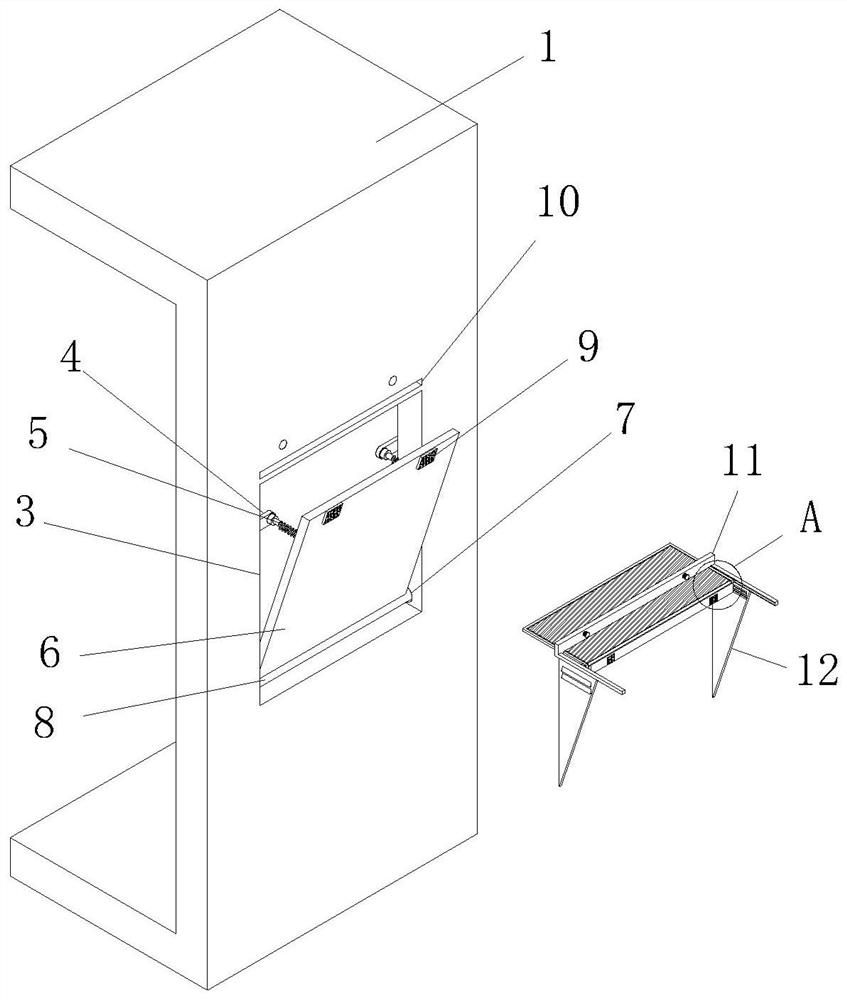
[0032] Example 1: Please refer to Figure 1-3, a comprehensive control box for a towel rapier loom, comprising a control box 1, the control box 1 is a rectangular hollow structure, the outer wall of the control box 1 is movably connected with a sliding door 2 through a hinge, the sliding door 2 is a rectangular structure, and the control box 1 There are two heat dissipation holes 3 on the outer wall of the control box 1, and the heat dissipation holes 3 are rectangular through holes. The outer wall of the control box 1 is provided with two through grooves 10, which are rectangular through holes. , the inner wall of the control box 1 is fixedly installed with four fixed blocks 4 at the positions corresponding to the two heat dissipation holes 3, and the inside of the fixed block 4 is fixedly equipped with an electric telescopic rod 5, which is an existing structure, and will not be described here. To repeat, there is a rotatable baffle 6 inside the heat dissipation hole 3, the ...

Embodiment 2

[0034] Embodiment two: on the basis of embodiment one, as Figure 6 The outer wall of the side plate 12 is provided with two side holes 28, the side holes 28 are rectangular through holes, the inside of the side hole 28 is fixedly equipped with a shroud 29, the shroud 29 is a rectangular inclined plate, and the shroud 29 is in a downwardly inclined state .

[0035] Working principle: through the side hole 28 is fixedly installed with the hood 29, the hood 29 is in a downward sloping state, part of the heat inside the control box 1 can flow out through the side hole 28, and at the same time, when the side plate 12 is used to block When the gaps on both sides of the board 6 are blocked, the downwardly inclined shutter 29 prevents external dust from entering the inside of the control box 1 through the side hole 28 .

Embodiment 3

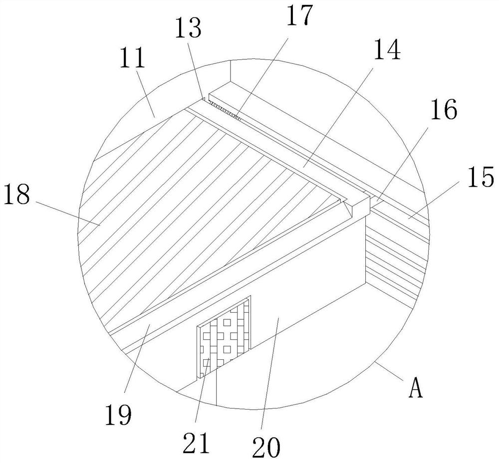
[0036] Embodiment three: on the basis of embodiment one, as Figure 4 , The bottom of the slide block 16 is provided with a draw-in groove 22, the draw-in groove 22 is a three-quarter spherical groove, and the inside of the draw-in groove 22 is movable with a ball 23, and the ball 23 is a spherical structure.

[0037] Working principle: Balls 23 are movably installed inside the card slot 22, and the slider 16 slides inside the chute 15 to drive the screen frame 14 to slide. When the slider 16 slides inside the chute 15, the balls 23 can slide Friction is converted into rolling friction, which reduces the frictional force, thereby facilitating the sliding of the screen frame 14.


PUM


Abstract

The invention discloses a comprehensive control box of a towel rapier loom, and belongs to the technical field of control boxes. The comprehensive control box comprises a control box body; the outer wall of the control box body is movably connected with a sliding door through hinges; and two heat dissipation holes are formed in the outer wall of the control box body. Electric telescopic rods push baffles to rotate towards the outer sides of the heat dissipation holes; when the baffles rotate to the outer sides of the heat dissipation holes, certain gaps are formed between the tops and the front and rear sides of the baffles and the control box body; second magnets and first magnets repel each other, at the moment, screen frames penetrate through connecting grooves and penetrating grooves to slide outwards under the action of external force, the screen frames slide outwards under the action of external force to cover the gaps formed in the tops of the baffles, and meanwhile two side plates at the bottom of each fixed frame can cover the gaps in the two sides of the corresponding baffle; and when the electric telescopic rods retract, the baffles can be driven to rotate back into the heat dissipation holes, at the moment, the screen frames are stored in the control box body under the acting force of springs, and therefore filter screens are stored when heat dissipation is not needed.

Description

technical field [0001] The invention relates to the technical field of control boxes, in particular to a comprehensive control box for a towel rapier loom. Background technique [0002] The textile machine controller is controlled by a single-chip microcomputer, which automatically detects the load current and sets the protection parameters. It has various protection functions such as locked-rotor, overload, phase loss, disconnection, and short circuit. It is responsive and reliable. It is also equipped with a special protective shell. The terminal block can effectively protect the motor of the knitting machine, but it will generate a lot of heat when the controller is running, and it will be difficult to ensure the dustproof effect while the controller is in use. [0003] According to the structure of the control box disclosed by the Chinese patent (the authorized publication number is CN209731775U), it includes the box body, the outer wall of the box is provided with an ou...

Claims


Application Information

Patent Timeline
Patent Type & Authority Applications(China)
IPC IPC(8): D03J1/00D03D51/02
CPCD03D51/02D03J1/002D03J1/008
Inventor 倪家炜
Owner 绍兴市嘉纬电子科技有限公司
Why Eureka
Try Eureka