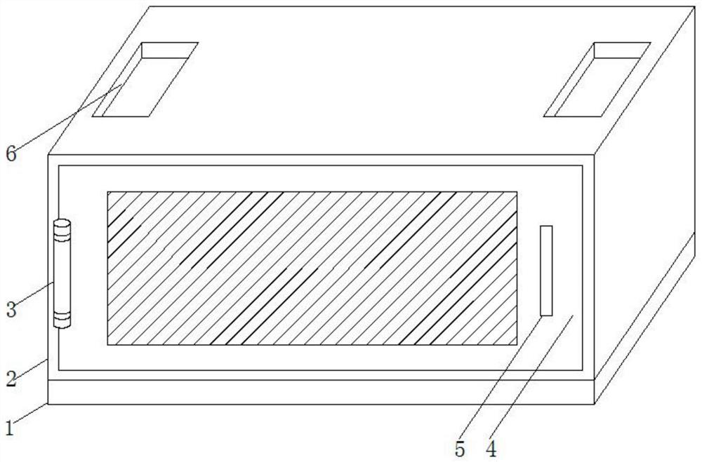
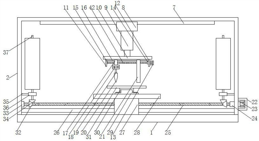
[0026] see Figure 1-4 , the present invention provides a technical solution: an integrated drilling and hair-planting machine, comprising a device bottom plate 1, and the top of the device bottom plate 1 is provided with a drilling and hair-planting integrated mechanism and a rotating mechanism;
[0027] The integrated drilling and hair planting mechanism includes a first electric sliding rail 7, a first electric sliding block 8, an electric telescopic cylinder 9, a first fixing plate 11, a second fixing plate 12, a first motor 13, a first motor shaft 14, The first threaded rod 42, the first bearing 15, the first moving block 17, the second motor 18, the second motor shaft 19, the rotating rod 37, the drill bit 20 and the hair planting head 21; the top of the device bottom plate 1 is bolted with a device Box 2, the top of the device box 2 is bolted with a first electric sliding rail 7, the bottom of the first electric sliding rail 7 is slidably connected with a first electric slider 8, and the bottom of the first electric slider 8 is slidably connected An electric telescopic cylinder 9 is threadedly connected, the bottom of the electric telescopic cylinder 9 is bolted with a fixed strip 10, and the left and right sides of the bottom of the fixed strip 10 are respectively fixed with a first fixed plate 11 and a second fixed plate 12. A first motor 13 is bolted on the right side of the second fixing plate 12 , a first motor shaft 14 is connected on the left side of the first motor 13 , and the left side of the first motor shaft 14 is fixedly connected through the second fixing plate 12 There is a first threaded rod 42, the left side of the first threaded rod 42 is rotatably connected to the first bearing 15 through the hair planting head 21 and the first moving block 17, and the left side of the first bearing 15 is fixedly connected to a first fixed Plate 11, the first threaded rod 42 is threadedly connected with the first moving block 17 and the screw holes in the hair planting head 21, the bottom of the first moving block 17 is bolted with a second motor 18, and the second motor 18 A second motor shaft 19 is connected to the bottom, and a drill bit 20 is fixedly connected to the bottom of the second motor shaft 19;
[0028]The rotating mechanism includes a motor protective cover 22, a third motor 23, a third motor shaft 24, a second threaded rod 25, a second moving block 27, a second bearing 33, a first bevel gear 32, a second bevel gear 34, A fixed rod 35, a third bearing 36 and a rotating rod 37; a motor protective cover 22 is bolted to the bottom of the right side of the device box 2, and a third motor 23 is bolted to the inner right side of the motor protective cover 22. The left side of the third motor 23 is connected with a third motor shaft 24, the left side of the third motor shaft 24 is fixedly connected with a second threaded rod 25 through the device casing 2, and the left side of the second threaded rod 25 passes through the second threaded rod 25. The moving block 27 is rotatably connected with a second bearing 33 , and the left side of the second bearing 33 is fixedly connected with the device box 2 , the second threaded rod 25 is threadedly connected with the screw hole in the second moving block 27 , the second A first bevel gear 32 runs through the left and right ends of the outer side of the threaded rod 25, and a second threaded rod 34 is fixedly connected to the inside of the first bevel gear 32. The bottom of the left and right sides of the inner wall of the device box 2 is fixedly connected with a fixed rod 35. The other end of the fixed rod 35 is fixedly connected with a third bearing 36, a rotating rod 37 is rotatably connected inside the third bearing 36, and a second bevel gear 34 is fixedly connected at the bottom of the rotating rod 37. The top of the second bevel gear 34 is engaged with the first bevel gear 32 .
[0029] It should be noted that, by disposing the first moving block 16 and the hair transplanting head 21 on the first threaded rod 42 , not only can the drill bit and the hair transplanting head 21 on the moving block be used to move the hole from right to left on the object , in the process of drilling to the left, the hair planting head 21 can be used to directly plant hair on the hole, and the drilling mechanism and the hair planting mechanism can be integrated, eliminating the need for drilling and planting respectively, and can be adjusted through the threaded rod. The distance between the drill bit and the hair-planting head 21 is suitable for drilling and hair-planting with different distances, which improves the adjustability of the device. Because the second threaded rod 25 is provided with the first bevel gear 32 and the first bevel gear on the rotating rod 37. During the rotation of the second threaded rod 25, the two bevel gears 34 will drive the two bevel gears to rotate, thereby making the rotating rod 37 rotate, and the rotating rod 37 can drive the rotation of the cylindrical object, so as to use the external drill bit The object is drilled for hair transplant.
[0030] In this example see figure 1 , the top of the second moving block 27 is bolted with a first connecting plate 28, the middle of the top of the first connecting plate 28 is bolted with a second electric slide rail 29, and the top of the second electric slide rail 29 is slidably connected with a first connecting plate 28. Two electric sliders 30, the top of the second electric slider 30 is bolted with a second connecting plate 31.
[0031] In this example see figure 1 , opposite threads are provided on the left and right sides of the outer side of the first threaded rod 42 .
[0032] In this example see figure 1 The second connecting plate 31 is provided with a plurality of circular holes 38 equidistantly, and a vacuum pump 39 is bolted in the circular hole 38, and the upper and lower ends of the vacuum pump 39 are connected with vacuum suction cups 40.
[0033] It should be noted that since the second fixing plate 12 is provided with the circular hole 38 and the vacuum pump 39 , the vacuum suction cup 40 on the vacuum pump 39 can be used to adsorb and fix the object that needs to be drilled and planted, while the first fixing plate 11 The bottom is provided with a second electric sliding rail 29 to enable the second fixing plate 12 to move longitudinally.
[0034] In this example see figure 1 , an electrostatic plate 41 is embedded and fixed on the top of the first connecting plate 28 , and the electrostatic plate 41 is electrically connected to an external electrostatic generator.
[0035] It should be noted that, since the electrostatic plate 41 is provided on the first fixing plate 11, the electrostatic plate 41 can be used to adsorb the fallen bristles and floating bristles, so as to collect the bristles and avoid the bristles from being scattered.
[0036] In this example see figure 1 The inner top of the first moving block 17 and the hair-planting head 21 both have a first moving rod 16, and the left and right sides of the first moving rod 16 are fixedly connected with a first fixing plate 11 and a second fixing plate 12 respectively.
[0037] In this example see figure 1 The inner bottom end of the second moving block 27 penetrates a second moving rod 26 , and the left and right sides of the second moving rod 26 are fixedly connected with the device box 2 .
[0038] In this example see figure 1 , a hinge 3 is fixedly connected to the left end of the front side of the device box 2, a box baffle 4 is rotatably connected to the front side of the hinge 3, and a handle 5 is welded to the right end of the front side of the box baffle 4. The device box Square holes 6 are opened on the left and right sides of the top of the body 2 .
[0039] When an all-in-one drilling and hair-planting machine is used, it should be noted that the electric telescopic cylinder 9, the first electric slide rail 7, the second electric slide rail 29, the first motor 13, the second motor 18, the third motor The motor 23, the vacuum pump 39 and the hair planting head 21 are electrically connected to the external power supply, and then the electric telescopic cylinder 9, the first electric slide rail 7, the second electric slide rail 29, the first motor 13, the second motor 18, the third The motor 23, the vacuum pump 39 and the hair planting head 21 are connected to the external control switch signal. After the connection is completed, the object is first placed on the second connecting plate 31, then the vacuum pump 39 is turned on, and the object is carried out by the vacuum suction cup 40 on the vacuum pump 39. Fixing, after fixing, turn on the first motor 13, the first motor 13 drives the first motor shaft 14, the first motor shaft 14 drives the first threaded rod 42, and the first threaded rod 42 drives the first moving block 17 and the hair planting machine The head 21 moves at the same time to adjust the distance between the drill bit 20 and the hair planting head 21. After the adjustment is completed, the first electric slide rail 7 and the second motor 18 are turned on. The second motor 18 drives the second motor shaft 19 and the second motor shaft 19 Drive the drill bit 20, after starting the electric telescopic cylinder 9 to move up and down, the drill bit 20 and the hair-planting head 21 can be driven to move up and down, and the first electric sliding rail 7 drives the drill bit 20 and the hair-planting head 21. 20 for drilling, and the hair-planting head 21 directly performs hair-planting on the drilled hole. When the third motor 23 is turned on, the third motor 23 will drive the second threaded rod 25, and the second threaded rod 25 will drive the first bevel gear 32. The first bevel gear 32 drives the second bevel gear 34, the second bevel gear 34 drives the rotating rod 37, and the electrostatic plate 41 is opened to adsorb the fallen bristles and floating bristles, thereby collecting the bristles and avoiding the bristles from being scattered. The present invention is an integrated machine for drilling and planting hair, comprising: 1. a device bottom plate; 2. a device box; 3. a hinge; 4. a box baffle; 5. a handle; 6. a square hole; ; 8, the first electric slider; 9, the electric telescopic cylinder; 10, the fixed strip; 11, the first fixed plate; 12, the second fixed plate; 13, the first motor; 14, the first motor shaft; 15, The first bearing; 16, the first moving rod; 17, the first moving block; 18, the second motor; 19, the second motor shaft; 20, the drill bit; 21, the hair planting head; 22, the motor protective cover; Three motors; 24, the third motor shaft; 25, the second threaded rod; 26, the second moving rod; 27, the second moving block; 28, the first connecting plate; 29, the second electric slide rail; 30, the second Electric slider; 31, second connecting plate; 32, first bevel gear; 33, second bearing; 34, second bevel gear; 35, fixed rod; 36, third bearing; 37, rotating rod; 38, circle hole; 39, vacuum pump; 40, vacuum suction cup; 41, electrostatic plate; 42, the first threaded rod, the components are all common standard parts or components known to those skilled in the art, and their structures and principles can be adopted by those skilled in the art Known from technical manuals or by routine experimental methods.