Single-duct aircraft

An aircraft and ducting technology, applied in the field of ducted aircraft, can solve the problems of reducing the efficiency and power of single ducted aircraft, increasing airflow disturbance and resistance, etc.

Pending Publication Date: 2022-07-26
SHENZHEN UNIV
View PDF1 Cites 0 Cited by
  • Summary
  • Abstract
  • Description
  • Claims
  • Application Information

AI Technical Summary

Problems solved by technology

The propeller of this invention is installed on the central shaft, and the central shaft needs to be supported by a bracket, which i

Method used


Image

  • Single-duct aircraft
  • Single-duct aircraft
  • Single-duct aircraft

Examples


Embodiment Construction

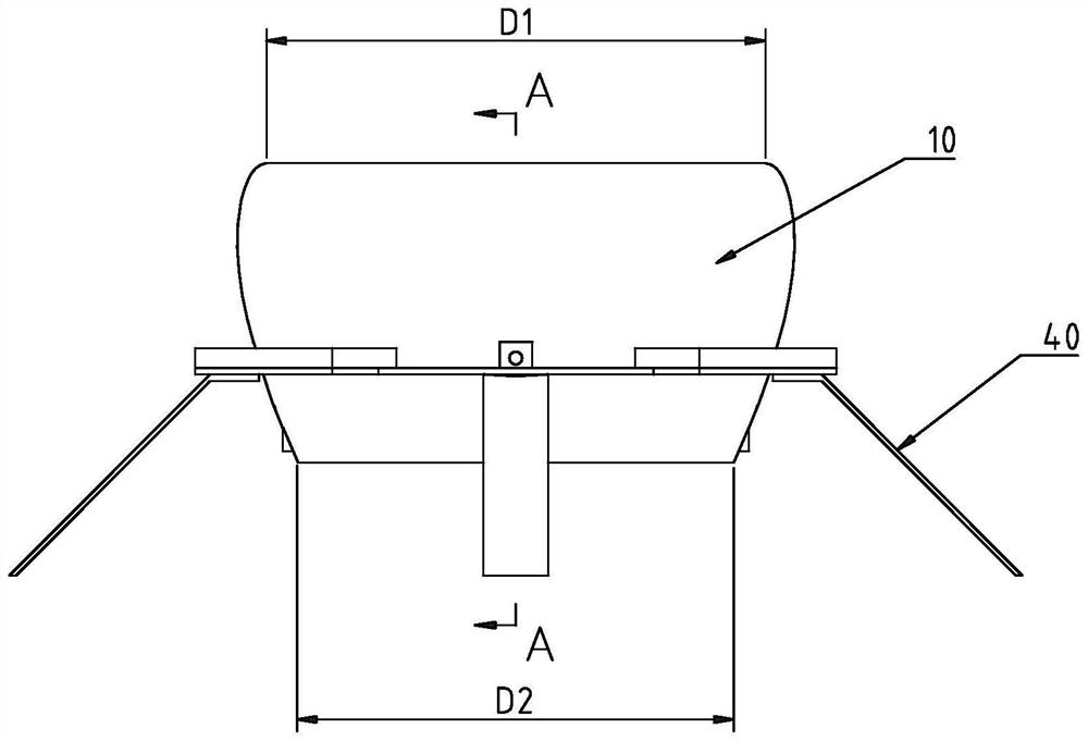
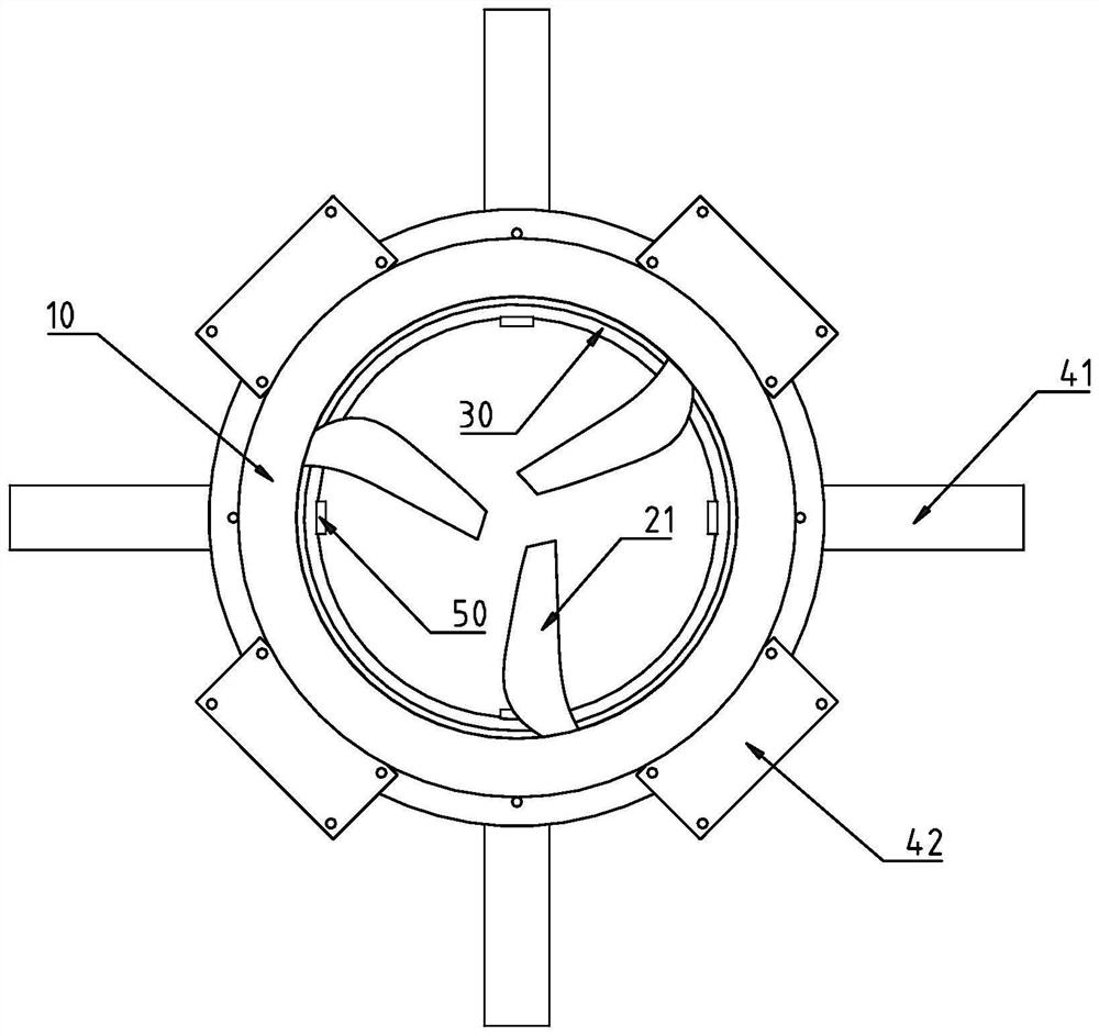
[0028] The structure of the single-duct 10 aircraft in the embodiment of the present invention is as follows: Figure 1 to Figure 10 As shown, it includes an annular duct 10 , a propeller 20 , a propeller 20 drive motor, a landing gear 40 and four dual jet exciters 50 .

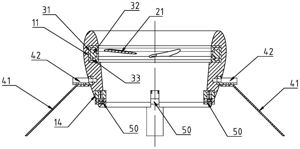
[0029] The axis of the duct 10 is arranged vertically, and the drive motor of the propeller 20 is a shaftless motor 30 . The inner wall of the duct 10 has an annular groove 11 , the stator 31 of the shaftless motor 30 is embedded in the annular groove 11 , and the rotor 32 of the shaftless motor 30 is installed in the stator 31 through the bearing 33 .

[0030] The plurality of blades of the propeller 20 are fixed on the annular rotor 32 of the shaftless motor 30 .

[0031] The radial outer ends of the three blades 21 of the propeller 20 are fixed on the annular rotor 32 of the shaftless motor 30 , and the inner ends of the three blades 21 of the propeller 20 cantilever.

[0032] The longitudinal section of...


PUM


Abstract

The invention discloses a single-duct aircraft which comprises an annular duct, a propeller and a propeller driving motor, the axis of the duct is vertically arranged, the propeller driving motor is a shaftless motor, a stator of the shaftless motor is fixed on the inner wall of the duct, and a plurality of blades of the propeller are fixed on an annular rotor of the shaftless motor. The propellers are installed on the annular rotors of the shaftless motors, a support does not need to be installed in the duct, the internal resistance of the duct is small, and the ducted aircraft is large in power and high in efficiency.

Description

[Technical field] [0001] The present invention relates to a ducted aircraft, in particular to a single-ducted aircraft. [Background technique] [0002] Ducted fan aircraft has the advantages of compact structure, good maneuverability, strong environmental adaptability, etc., and the scope of use has been extended to the three major fields of military, civil and scientific research. focus on. The structure of the ducted UAV includes: annular wing (ducted), paddle disc, tail rudder and fuselage. Among them, the annular wing and fan play an important role in the forward flight of the ducted fan UAV, and the driving force of the whole aircraft is provided by this. When the annular wing UAV takes off on the vertical plane, the reaction force of the propeller on the air and the additional thrust of the annular wing act together; the yaw, pitch and roll of the ducted fan aircraft during forward flight are determined by Control the role of the rudder surface to achieve. [0003]...

Claims


Application Information

Patent Timeline
IPC IPC(8): B64C11/00B64C27/20B64D27/24
CPCB64C11/001B64C27/20B64D27/24B64U50/19B64U50/14
Inventor 巩伟杰翁伟鑫陈宏杨忠华庄饰余燕陈欣罗浩张国静陈泽通黎熠哲韩芮斌李宗信郭婷黄润光
Owner SHENZHEN UNIV
Why Eureka
Try Eureka