UPS device with passive balance

A balanced, converter technology, applied in the field of converters, which can solve problems such as unbalanced voltage and current, lack of resistance to faults, etc.

Pending Publication Date: 2022-07-26
ABB (SCHWEIZ) AG
View PDF0 Cites 0 Cited by
  • Summary
  • Abstract
  • Description
  • Claims
  • Application Information

AI Technical Summary

Problems solved by technology

However, such circuits can suffer from unbalanced voltages and currents and a lack of resistance to failure

Method used


Image

  • UPS device with passive balance
  • UPS device with passive balance
  • UPS device with passive balance

Examples


Embodiment Construction

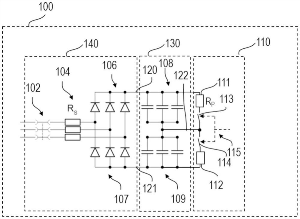
[0033] figure 1 A diagram of an AC / DC converter 100 according to an embodiment is shown. More complicatedly, figure 1Split DC link 130 is shown including DC capacitor 108 and DC capacitor 109 including three electrolytic capacitors connected in parallel between positive line 120 and flow midpoint 122, and DC capacitor 109 correspondingly including a parallel connection Three electrolytic capacitors between negative line 121 and flow midpoint 122. figure 1 Further shown is an AC precharge circuit 140 comprising three phase diode bridges 106 , 107 with series current limiting resistors 104 and AC input junction contacts or relays 102 . also, figure 1 Resistor circuit 110 is shown including resistor 111 and contact 113 in series and parallel with capacitor 108 , and resistor 112 and contact 114 in series and parallel with capacitor 109 . The two contacts 113, 114 drawn may be the two contacts of the same switch 115 to prevent accidental insertion of parallel resistors on a si...


PUM


Abstract

The invention relates to a UPS device with passive balance. The invention relates to a converter (100, 200), which comprises a converter (100, 200). 200) includes a DC split link (130) having a positive line (120), a floating midpoint (122) and a negative DC line (121), a first DC capacitor (108) arranged between the positive line and the floating midpoint, a second DC capacitor (109) arranged between the negative line (121) and the floating midpoint (122), a first resistor (111) arranged in parallel with the first DC capacitor (108), a second resistor (112) arranged in parallel with the second DC capacitor (109). The first resistor (111) and the second resistor (112) are configured to be engaged during a pre-charge phase of the converter (100, 200).

Description

technical field [0001] The present invention relates to converters, uninterruptible power supply (UPS) equipment, controllers for uninterruptible power supply equipment, use of switchable resistors to provide DC voltage balancing, and voltage balancing of DC split links in converters Methods. Background technique [0002] In a UPS with an AC / DC booster, the DC link needs to be precharged. A converter such as in a UPS device may include a precharge circuit connected to the AC and DC lines of the converter to precharge the capacitors when the converter starts up to avoid use when the circuit is turned on High current to load capacitors. In particular, voltage balancing can be an issue on units with split DC links. This is not the case in a 4-wire system, as the midpoint voltage is fixed by bonding, however, in a 3-wire distribution where the midpoint is floating, this can become a problem. Typically, precharging can be accomplished by an AC precharging circuit that include...

Claims


Application Information

Patent Timeline
IPC IPC(8): H02J7/10H02J9/06
CPCH02J7/06H02J7/345H02J9/06H02J2207/20H02J2207/50H02M1/36H02M7/06H02J7/0014H02J9/061
Inventor 洛伦佐·琼蒂尼
Owner ABB (SCHWEIZ) AG
Why Eureka
Try Eureka