Microwell plate for containing plurality of samples

A microplate and sample technology, applied in the field of microplate, can solve the problems of reducing experimental output and so on

Pending Publication Date: 2022-07-29
LEICA MICROSYSTEMS CMS GMBH
2 Cites 0 Cited by

AI-Extracted Technical Summary

Problems solved by technology

Additionally, moving samples from one microplate...

Method used

[0042] Additionally, the interior surfaces of the compartments 104, 106 may alternatively or additionally be coated with a low adhesion coating. In particular,...

Abstract

A microwell plate (100, 400) for containing a plurality of samples (612), comprising a plurality of sample cavities (102), each sample cavity (102) comprising at least one separating element (120, 402) separating the sample cavity (102) into at least one donor compartment (104) and an acceptor compartment (106). The partition element (120, 402) is configured to receive one of the samples within one of the donor compartment (104) or the acceptor compartment (106) when the microwell plate (100, 400) is in the first orientation. The separating element (120, 402) is further configured to allow the sample (612) to be transferred at least from the donor compartment (104) to the acceptor compartment (106) of one of the sample cavities (102) when the microplate (100, 400) is in the second orientation. Another aspect is a method for transferring a sample between compartments (104, 106) of a microwell plate (100, 400).

Application Domain

Laboratory glasswaresSupporting apparatus +3

Technology Topic

Molecular biologyBiophysics +2

Image

  • Microwell plate for containing plurality of samples
  • Microwell plate for containing plurality of samples
  • Microwell plate for containing plurality of samples

Examples

  • Experimental program(1)

Example Embodiment

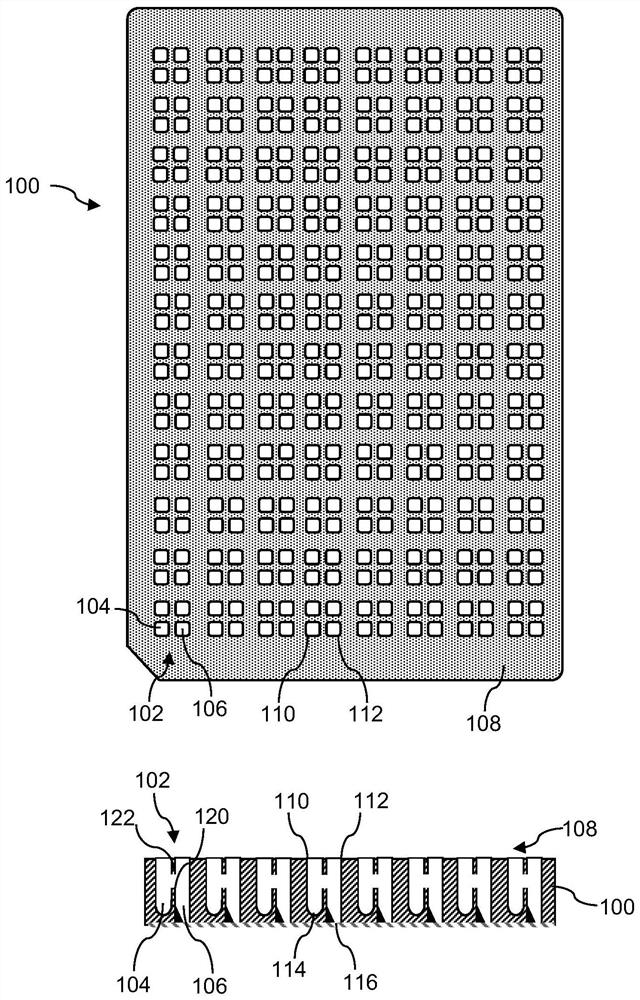
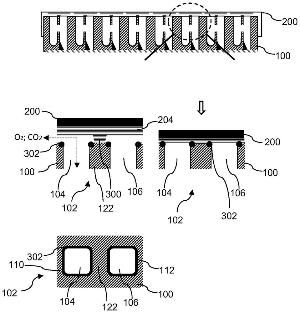
[0031] figure 1 A schematic top view and corresponding cross-sectional view of the microplate 100 are shown. Microplate 100 includes 192 sample chambers 102 arranged in an 8 by 24 grid. Each cavity 102 includes a donor compartment 104 and an acceptor compartment 106 . Thus, the microplate 100 includes 384 compartments 104 , 106 . Alternatively, the microplate 100 may have additional or fewer sample cavities 102 .
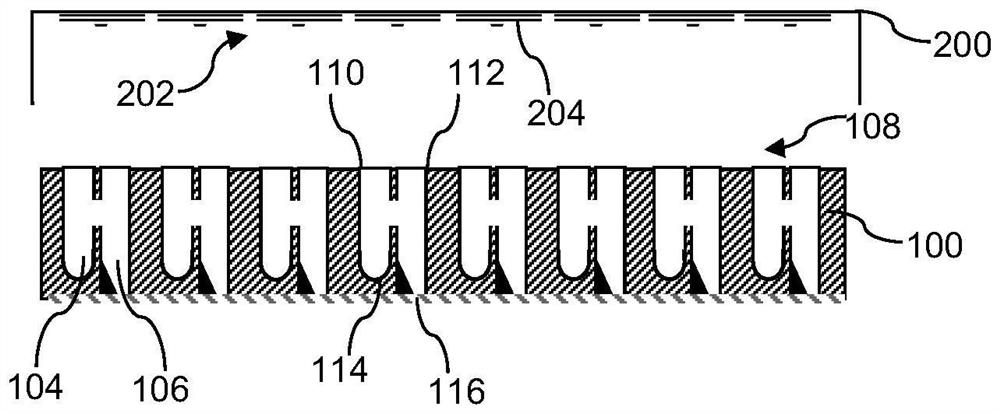
[0032] Each of the compartments 104 , 106 is open towards the top side 108 of the microplate 100 and includes openings, in particular the donor compartment 104 includes the donor opening 110 and the acceptor compartment 106 includes the acceptor opening 112 . The openings 110, 112 allow individual access to the interior of the respective compartments 104, 106, eg, for individually adding or removing samples using a manual pipette or using a liquid handling robot. figure 1 The openings 110, 112 of the microplate 100 are rectangular in shape. Similarly, the side walls of the compartments 104 , 106 are rectangular in a plane parallel to the top side 108 . Alternatively, the openings 110, 112 and the compartments 104, 106 may have different geometries, eg they may be circular.
[0033] Preferably, all cavities 102 of the microplate 100 have the same size and geometry. Alternatively, some or all of the cavities 102 of the microplate 100 may vary in size and geometry.
[0034] Furthermore, the top view shows that the compartments 104 , 106 are arranged in groups of four on the top side 110 of the microplate 100 . Alternatively, the compartments 104, 106 may be arranged uniformly on the top side 110 of the microplate 100, or they may be arranged according to different patterns.
[0035] Each of the compartments 104 , 106 includes a bottom, in particular the donor compartment 104 includes a donor bottom 114 and the acceptor compartment 106 includes an acceptor bottom 116 . The donor bottom 114 has a rounded inner surface, particularly a concave or hemispherical surface, and is commonly referred to as a rounded bottom. The shape of the donor bottom 114 of the microplate 100 is formed for cell culture to generate cell populations such as spheroids, microtissues, tumoroids or organoids, particularly for use in suspension without scaffolds three-dimensional cell culture. Alternatively, the donor bottom 114 may be V-shaped.
[0036]The receptor bottom 116 is flat. In addition, the receptor base 116 is transparent, in particular an optically transparent plane-parallel plate. For example, receptor base 116 may be fabricated from glass or optical grade polystyrene, cyclic olefin copolymer, or polycarbonate. Thus, the interior of the receptor compartment 106 can be viewed through the receptor bottom 120, for example with a microscope, particularly with an inverted microscope. This allows, for example, observation of the sample in the receptor compartment 106 with a minimal amount of optical aberration. Furthermore, when the sample is imaged through the receptor bottom 116, the distance between the sample and the microscope objective is reduced compared to imaging the sample through the receptor opening 112 of the microplate 100. This is particularly advantageous when using high numerical aperture objectives, which require a short working distance between the objective's front lens and the imaged sample.
[0037] The compartments 104 , 106 of each of the sample chambers 102 are separated from each other by a separating element 120 . Separation element 120 is formed and arranged to contain a sample in one of compartments 104 , 106 , particularly donor compartment 104 , when microplate 100 is in the first orientation. In the first orientation, the microplate 100 is in a horizontal orientation with the microplate 100 resting on the bottom side of the microplate 100 and the bottom side of the microplate 100 is opposite and parallel to the top side 108 of the microplate 100 . Thus, when the microplate 100 is in the first orientation, the sample is contained in one of the compartments 104 , 106 such that the sample does not spill over into the one of the compartments 104 , 106 of the sample chamber 102 in another compartment. Furthermore, when the microplate 100 is incubated and moved within the plane of the top side 108 of the microplate 100, the sample does not spill.
[0038] Furthermore, the separation element 120 extends along a line perpendicular to the top side 108 of the microplate 100 and between the donor compartment 104 and the acceptor compartment 106 of one of the sample chambers 102 . Thus, the dividing element 120 forms part of one of the side walls of each compartment 104 , 106 . The side walls of each compartment 104 , 106 extend from the bottom 114 , 116 of the compartment 104 , 106 to the top side 108 of the microplate 100 . Instead, the dividing elements 120 extend from the bottoms 114 , 116 of the compartments 104 , 106 , but are generally shorter than the side walls of the compartments 104 , 106 .
[0039] Furthermore, the separation element 120 may include portions configured to separate the compartments 104 , 106 and allow sample transfer from one compartment 104 , 106 of one of the sample chambers 102 to the other compartment 104 , 106 . Separator element 120 of microplate 100 includes upper portion 122, in figure 1 The corresponding lower part is designated by the reference numeral 120 in the . There is an opening between the lower portion 120 and the upper portion 122 that places the donor compartment 104 and the acceptor compartment 106 in fluid communication, particularly when the microplate 100 is in the second orientation. In an alternative embodiment, the microplate 100 does not have the upper portion 122 .
[0040] Alternatively, each cavity 102 may have additional compartments, eg, the cavity 102 may include three compartments. Additionally, each cavity 102 may include additional dividing elements 120, particularly for separating additional compartments.
[0041] In another alternative, the compartments 104, 106, particularly the receptor compartment 106, may be pre-filled with chemical compounds, biochemical compounds and/or organisms. The inner surfaces of the compartments 104, 106 may be coated with these compounds or organisms, in particular. These compounds can be, for example, drugs, small molecules, metabolites, proteins, reagents, siRNAs, enzymes, and compounds for gene editing (eg, CRISPR). These organisms can be, for example, algae, archaea, fungi, unicellular eukaryotes, multicellular organisms, parasites, pathogens, viruses and prions. In addition, these compounds and organisms can be lyophilized and/or encapsulated. Additionally, these compounds and organisms may be placed in suspension when adding or transferring liquid samples to the compartments 104, 106.
[0042] Additionally, the interior surfaces of the compartments 104, 106 may alternatively or additionally be coated with a low adhesion coating. The inner surface of the donor compartment 104 may be coated, among other things, with a low adhesion coating to facilitate three-dimensional culture of the spheroids in suspension.
[0043] figure 2 is a schematic cross-sectional view of a microplate 100 with a lid 200. Elements having the same structure or function have the same reference numerals. The lid 200 includes a surface 202 oriented toward the top side 108 of the microplate 100 . The surface 202 of the lid 200 includes seals 204 each arranged on the surface 202 such that they are aligned with the compartments 104 , 106 , in particular with the openings 110 , 112 of the compartments 104 , 106 of the cavity 102 . Alternatively, the seal 204 may be sized to cover the entire top side 108 of the microplate 100 .
[0044] image 3 is a schematic cross-sectional view of the microplate 100 with the cover 200 resting on the top side of the microplate 100 and a detailed schematic cross-sectional view of the sample cavity 102 of the microplate 100 with the cover 200 and the sample cavity Schematic top view of 102 .
[0045] The lid 200 includes a flexible spacer element 300 that keeps the surface 202 and seal 204 of the lid 200 at a distance from the top side 108 of the microplate 100 when the lid 200 is not pressed against the top side 108 . This allows mass transfer between the interior and exterior of the cavity 102, in particular gases such as oxygen and carbon dioxide can be exchanged between the interior and exterior of the cavity 102. When the lid 200 is pressed against the top side 108 , the flexible spacer element 300 is compressed and the lid 200 , and in particular the seal 204 , seals the cavity 102 . Therefore, the contents of the cavity 102 , and in particular the contents of the compartments 104 , 106 , cannot escape or leak from the cavity 102 .
[0046] Additionally or alternatively, the microplate 100 may include a circumferential seal 302 disposed around the openings 110 , 112 of the compartments 104 , 106 . These seals 302 are configured to seal the cavity 102 of the microplate 100 when the lid 200 is pressed against the top side 108 of the microplate 100 .
[0047] Figure 4 is a schematic cross-sectional view of a microplate 400 with lid 100. The microplate 400 includes a partition element 402 configured to guide the sample as it is transferred from the donor compartment 104 to the acceptor compartment 106 . Separation element 402 includes in particular a ramp 404 which guides the sample from donor compartment 104 to recipient compartment 106 when transferring the sample to recipient compartment 106 .
[0048] Figure 5 is a schematic cross-sectional view of a microplate 100 with a lid 500 . The lid 500 includes a seal 502 configured to fit into the opening 110 of the donor compartment 104 . Seal 502 seals donor compartment 104 when lid 500 is pressed against microplate 100 . In addition, the seal 502 is formed with an inclined surface 504 configured as a guide element to guide the sample as it is transferred from the donor compartment 104 to the acceptor compartment 106 . Additionally, the lid 500 includes a seal 506 that seals the opening 112 of the receptor compartment 106 .
[0049] Image 6 A flowchart showing the steps of a method for transferring a sample from the donor compartment 104 to the acceptor compartment 106 of the sample chamber 102 of the microplate 100 is shown.
[0050] In a first step denoted by reference numeral S600, the donor compartment 104 of the microplate 100 is filled with liquid growth medium and seeded with a small amount of cells 610. Additionally, the lid 200 is placed on the microplate 100 before the microplate 100 is incubated and shaken in an orbital motion in the first orientation.
[0051] In step S602, the incubation is stopped after the cells 610 have formed spheroids 612 or organoids. The spheroid 612 is also referred to as a sample and consists of a population of multiple cells 610 of a single type or a series of different types.
[0052] In step S604, the microplate 100 transitions from the first orientation to the second orientation. In the second orientation, the donor compartment 104 is positioned above the acceptor compartment 106 such that the contents of the donor compartment 104 , including the spheroids 612 , flow into the acceptor compartment 106 . The spheroid 612 in particular passes through the opening between the lower part 120 and the upper part 122 of the separating element 120 .
[0053] In step S606, after the sample 612 is transferred into the receptor compartment 106, the microplate 100 transitions from the second orientation back to the first orientation.
[0054] During steps S604 and S606, particularly when the microplate 100 is rotated from the first orientation to the second orientation, the lid 200 of the microplate 100 is pressed against the top side 108 of the microplate 100 to ensure that the compartments 104, 106 leak-proof seal. This prevents leakage of the sample 612 from the compartments 104 , 106 .
[0055] In step S608, the microplate 100 is placed on a stage of a microscope, particularly an inverted microscope, in a first orientation. This allows analysis, in particular imaging, of the spheroids 612 through the transparent bottom 116 of the receptor compartment 106 by means of the microscope's objective 614, in particular with a high numerical aperture objective.
[0056] according to Image 6 The method of the flowchart in allows incubation of sample 612 in donor compartment 104 of microplate 100, subsequent transfer of sample 612 to acceptor compartment 106 of microplate 100 and sample 612 in acceptor compartment 106 imaging. Thus, the microplate 100 allows for the incubation and imaging of the samples 612, each under optimal conditions for their respective purposes, without the need for pipetting the samples to different microplates.
[0057] Steps S600 to S608 of the method may be automated, eg using laboratory robots.
[0058] Figure 7 is a flow diagram illustrating the transfer of a sample from the donor compartment 104 of the sample chamber 102 to the acceptor compartment 106 . Figure 7 A single sample chamber 102 is shown, which is representative of all sample chambers 102 of the microplate 100 . The sample chamber 102 is made according to Figure 5 The cover 500 covers and seals. Sample 612 is shown to include a liquid medium. The sample 612 is transferred from the donor compartment 104 to the acceptor compartment 106 by transitioning the sample chamber 102 and, accordingly, the microplate 100 from the first orientation to the second orientation and back to the first orientation.

PUM

no PUM

Description & Claims & Application Information

We can also present the details of the Description, Claims and Application information to help users get a comprehensive understanding of the technical details of the patent, such as background art, summary of invention, brief description of drawings, description of embodiments, and other original content. On the other hand, users can also determine the specific scope of protection of the technology through the list of claims; as well as understand the changes in the life cycle of the technology with the presentation of the patent timeline. Login to view more.
Why Eureka
Try Eureka