Detection device for intelligent machining

A detection device and intelligent machinery technology, applied in the direction of sorting, etc., can solve the problems of heavy manual labor, inaccurate detection, etc., and achieve the effect of easy screening or reprocessing

Pending Publication Date: 2022-07-29
YANTAI ENG & TECH COLLEGE YANTAI TECHNICIAN INST
View PDF0 Cites 2 Cited by
  • Summary
  • Abstract
  • Description
  • Claims
  • Application Information

AI Technical Summary

Problems solved by technology

[0003] The traditional size inspection is usually to compare and measure with a ruler, and then manually select the unqualified objects. Although this method can accurately detect the size of the objects, in practice, the amount of manual labor is relatively large, and after a long time of inspection, Artificial fatigue may cause inaccurate detection

Method used


Image

  • Detection device for intelligent machining
  • Detection device for intelligent machining
  • Detection device for intelligent machining

Examples


Embodiment 1

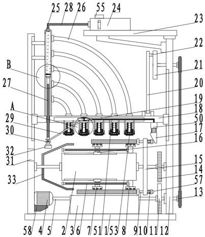
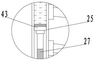
[0026] see Figure 1-6, a detection device for intelligent mechanical processing, comprising a base plate 1, and further comprising: a surrounding plate 12 fixedly arranged on both sides of the base plate 1, a feeding roller 2 is rotatably connected between the surrounding plates 12, and a movable plate 18 is arranged on one side of the feeding roller 2; Both sides of the movable plate 18 are slidably connected with the enclosure plate 12, and the detection mechanism 53 arranged on one side of the movable plate 18 includes a measuring cylinder 25, which is fixedly connected to the movable plate 18, and a sealing block 43 is slidably arranged in the measuring cylinder 25. , one side of the sealing block 43 is rotated and connected to the screw rod 27, one end of the screw rod 27 is threaded through the side wall of the measuring cylinder 25, and the end is fixedly connected to the mounting post 32, and one side of the movable plate 18 is fixedly set through the lower material cy...

Embodiment 2

[0030] see Figure 1-6 , the other content of this embodiment is the same as that of Embodiment 1, the difference is:

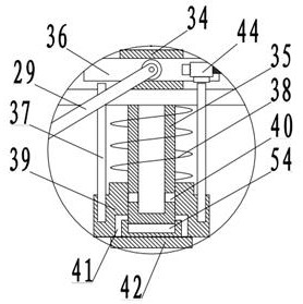
[0031] The transmission assembly includes an installation ring 30 that is rotatably sleeved and mounted on the installation post 32. One side of the installation ring 30 is hinged to the transmission arm 29, and one end of the transmission arm 29 is hingedly connected to the stop rod 36. A piston sleeve 39 at one end of the material cylinder 35, a material guide groove 41 is provided in the piston sleeve 39, a marking pad 42 is fixed at the end of the piston groove on one side of the material guide groove 41, and one end of the lower material cylinder 35 on the side of the piston sleeve 39 is sleeved A telescopic piece 38 is provided, and one side of the piston sleeve 39 is fixedly connected with the push rod 37 .

[0032] The feeding assembly 55 includes a top plate 23 fixed on the top of the enclosure plate 12, the top plate 23 is fixedly connected to the ...


PUM


Abstract

The invention discloses a detection device for intelligent machining, and relates to the technical field of mechanical detection, the detection device comprises a bottom plate, coamings fixedly arranged on two sides of the bottom plate, a feeding roller rotatably connected between the coamings, and a movable plate arranged on one side of the feeding roller; during actual detection, the screw rod is rotated according to actual requirements to drive the sealing block to move downwards, a dyeing material agent in the metering cylinder located on one side of the sealing block is fed into the discharging cylinder through the material guiding pipe, the sealing block is driven to move downwards, and the sealing block is driven to move downwards through the material guiding pipe. Meanwhile, an installation column at one end of the lead screw drives a sliding block to move to a standard detection position through a transmission assembly, when a movable plate moves downwards to make contact with a to-be-detected piece, a standard object and an object with the short size are marked, when an object with the long size is marked, a valve assembly is triggered, a trapezoidal block is driven to push the object under the action of a pneumatic telescopic cylinder, and the object is detected. And the materials are pushed out for screening.

Description

technical field [0001] The invention relates to the technical field of mechanical detection, in particular to a detection device for intelligent mechanical processing. Background technique [0002] There are many kinds of mechanical equipment. When it is running, some of its components and even themselves can perform different forms of mechanical movement. In the field of mechanical processing, the processing of many parts and components is often involved. Processing refers to cutting, grinding, crushing, etc., Machining refers to the process of changing the dimensions or performance of parts or workpieces through mechanical equipment. After the processing is completed, the size of the objects needs to be checked and the objects that meet the standards are selected. [0003] The traditional size inspection is generally to compare and measure with a ruler, and then manually select the unqualified objects. Although this method can accurately detect the size of the object, in p...

Claims


Application Information

Patent Timeline
IPC IPC(8): B07C5/04B07C5/36
CPCB07C5/04B07C5/362
Inventor 肖苏慧仇清海史丰荣
Owner YANTAI ENG & TECH COLLEGE YANTAI TECHNICIAN INST
Why Eureka
Try Eureka