
Turnover tongue shearing device of plastic winding drum turnover tongue device

A shearing device and plastic technology, applied in metal processing and other directions, can solve the problems of lack of chip collecting function and affecting the stable operation of the tongue turning shearing.

Pending Publication Date: 2022-07-29
胡艳娜
View PDF1 Cites 0 Cited by
  • Summary
  • Abstract
  • Description
  • Claims
  • Application Information

AI Technical Summary

Problems solved by technology

[0004] However, the technical solution provided by this patent does not have the function of collecting debris on the frame. When the cutting knife performs tongue-turning shearing on the plastic belt, the generated plastic debris will continue to accumulate on the frame. If the debris can be collected in time, there will be technical problems affecting the stable operation of the tongue turning shear

Method used


Image

  • Turnover tongue shearing device of plastic winding drum turnover tongue device
  • Turnover tongue shearing device of plastic winding drum turnover tongue device
  • Turnover tongue shearing device of plastic winding drum turnover tongue device

Examples


Embodiment 1

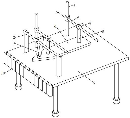
[0048] see Figure 1-2 , In the embodiment of the present invention, a tongue-turning shearing device of a plastic reel tongue-turning device includes:

[0049] Rack 1, the top plate of the rack 1 is in the shape of an inclined flat plate with an included angle of 20° to the horizontal plane, the top side of the rack 1 is fixedly installed with an adjusting rod 2 at the front of the outer front, and the top position of the adjusting rod 2 is movably installed with a cutting Knife 3, the front and rear parts of the left end of the top side outer surface of the frame 1 are located at the rear of the adjustment rod 2, respectively, and a fixed rod 4 is fixedly installed in the vertical direction. The middle end of the outer surface of the fixed rod 4 is installed with a first set Pipe 5, the right end position of the first sleeve 5 is fixedly installed with a cross bar 6 in a horizontal direction, the outer surface of the cross bar 6 is movably installed with a second sleeve 7, a...

Embodiment 2

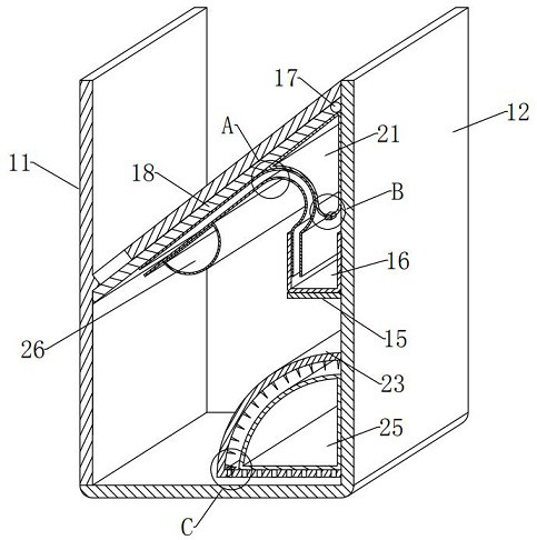
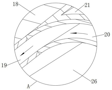
[0063] see Figure 2-4 and Figure 6-7 , the difference between the embodiment of the present invention and the embodiment 1 is that the preprocessing component 13 includes:

[0064]The fixing plate 15, the lower end of the right inner wall of the baffle 12 is fixedly installed with the fixing plate 15 in the horizontal direction, and the outer surfaces of the front and rear sides of the fixing plate 15 are fixedly installed at the lower part of the right end of the front and rear inner walls of the housing 11;

[0065] The material holding tank 16, the top side outer surface of the fixing plate 15 is fixedly installed with the material holding tank 16, and the appearance of the material holding tank 16 is in the shape of a letter "U" which is hollow inside on a longitudinal section, and the front and rear lengths of the material holding tank 16 are equal to The front and rear lengths of the fixed plate 15, the right outer surface of the material trough 16 is fixedly installe...

Embodiment 3

[0082] see figure 2 and Figure 5-7 , the difference between the embodiment of the present invention and the embodiment 1 is that the post-processing component 14 includes:

[0083] The bearing plate 23, the lower surface of the right inner wall of the baffle plate 12 is fixedly installed with the bearing plate 23, and the appearance of the bearing plate 23 in a longitudinal section is a 1 / 4 circle shape with an inner hollow, an open right end, a convex upper left, and a horizontal bottom end, The top of the right end of the carrier plate 23 is fixedly installed on the lower end surface of the right inner wall of the baffle plate 12, the bottom of the right end of the bearing plate 23 is fixedly installed on the bottom end surface of the right inner wall of the baffle plate 12, and the bottom end of the bearing plate 23 is equally adjacent to each other. Several through holes penetrating up and down;

[0084] The bearing plate 23 here has a 1 / 4 circle shape with an inner ho...


PUM


Abstract

The invention provides a tongue turning and shearing device of a plastic winding drum tongue turning device, which comprises a rack, and a top plate of the rack is in the shape of an inclined flat plate forming an included angle of 20 degrees with the horizontal plane; a plurality of scrap collecting assemblies capable of collecting plastic scraps cut by the cutting knife are fixedly installed on the outer surface of the front side of the rack in adjacent rows, and each scrap collecting assembly comprises a shell, a baffle, a pretreatment assembly capable of conducting primary treatment when the plastic scraps fall into the shell, and a post-treatment assembly capable of conducting final treatment after the plastic scraps fall into the shell; and a plurality of shells are fixedly mounted on the outer surface of the front side of the rack in adjacent rows. According to the tongue turning and shearing device of the tongue turning device of the plastic winding drum, the machine frame can have the scrap collecting function, in the process that a cutting knife conducts tongue turning and shearing on a plastic belt, generated plastic scraps cannot be continuously accumulated on the machine frame, the scraps can be collected in time, and the stable operation of tongue turning and shearing operation is guaranteed.

Description

technical field [0001] The invention relates to the technical field of plastic tape production, and more particularly, to a tongue-turning shearing device of a plastic reel tongue-turning device. Background technique [0002] At present, when the tongue turning device of the plastic reel is forming the turning tongue, the staff uses the cutter to cut the upper side of the plastic tape released from the plastic reel by virtue of their experience. Can not cut or cut too deep, resulting in different product quality, difficult to control. [0003] In view of the above problems, regarding the technical problem that the plastic reel tongue turning device is difficult to stably cut the plastic tape, after a large number of searches, the patent number of CN202020959665.6 is a kind of plastic reel tongue turning device. The device includes a rack, a spacer structure and a cutting structure, the plastic belt is located above the rack, the spacer structure includes spacers and a conne...

Claims


Application Information

Patent Timeline
Patent Type & Authority Applications(China)
IPC IPC(8): B26D7/00B26D7/18
CPCB26D7/00B26D7/1845B26D2007/0018
Inventor 胡艳娜
Owner 胡艳娜
Learn More