Fuel tank cap mounting device

A technology for installing devices and fuel tank caps, which is applied in the direction of power devices, transportation and packaging, and the arrangement combined with the fuel supply of internal combustion engines, etc. It can solve the problems of insufficient use effect, insufficient fixation effect, and inconvenient sealing, etc., and achieve a fixation effect Good, simple structure, fixed effect

Pending Publication Date: 2022-07-29
WUHU TYCO AUTOMOTIVE TECH CO LTD
View PDF0 Cites 0 Cited by
  • Summary
  • Abstract
  • Description
  • Claims
  • Application Information

AI Technical Summary

Problems solved by technology

[0003] Most of the current ordinary mailboxes have a mailbox cover. The traditional mailbox cover is mostly connected to the fuel filler port by threads. Because it is only fixed by one layer, the fixing effect is not good enough, and it is easy to loosen during long-term use. Threads are set at the mouth, which makes it inconvenient to seal, and the use effect is not good enough. For this reason, we need a fuel tank cap installation device

Method used


Image

  • Fuel tank cap mounting device
  • Fuel tank cap mounting device
  • Fuel tank cap mounting device

Examples


Embodiment 1

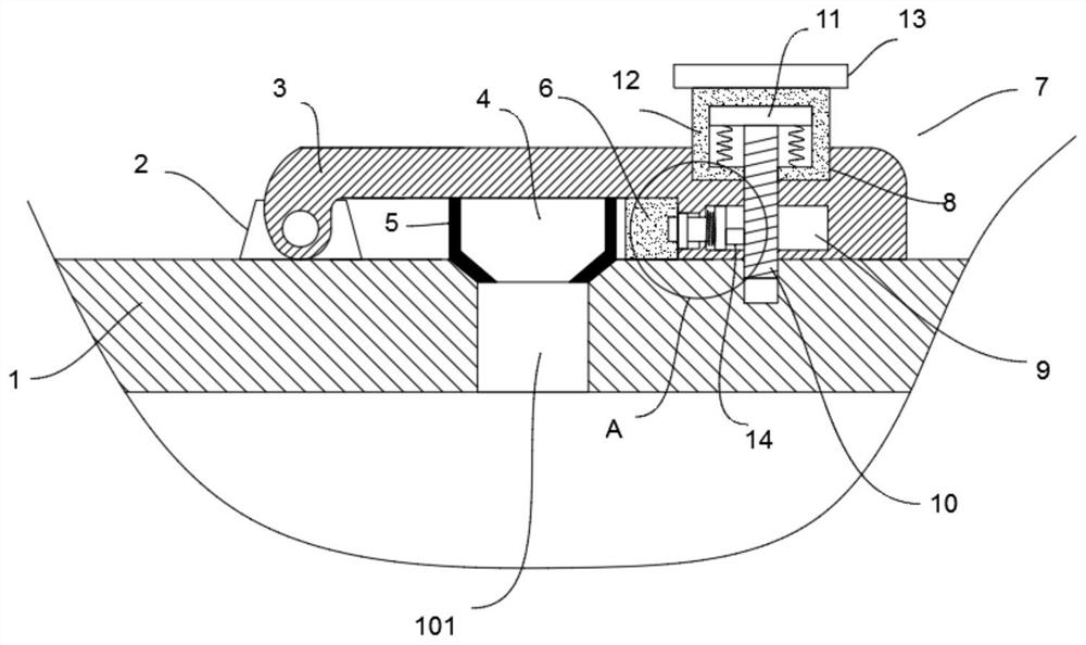
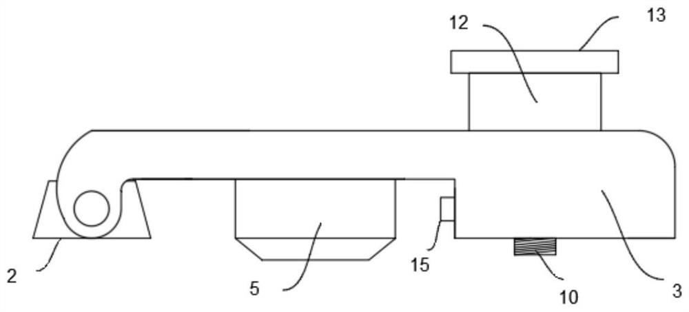
[0033] An installation device for a fuel tank cover, comprising a first fixing block 2 and a second fixing block 6 fixed on the tank wall 1 of the fuel tank, the first fixing block 2 and the second fixing block 6 are respectively arranged on both sides of the filling hole 101, A box cover plate 3 that covers the outside of the oil filling hole 101 is installed on a fixed block 2 through the rotation of the rotating shaft. A rubber sealing layer 5 is provided, and a first fixing mechanism 7 and a second fixing mechanism are provided at the end of the box cover 3 away from the first fixing block 2 . Specifically, the lower end shape of the blocking block 4 is conical.

[0034] It should be noted that the first fixing mechanism 7 includes a rectangular slot 8 and an installation cavity 9 disposed at one end of the box cover 3 away from the first fixing block 2 , and the rectangular slot 8 and the installation cavity 9 communicate with each other, and the rectangular slot 8 The i...

Embodiment 2

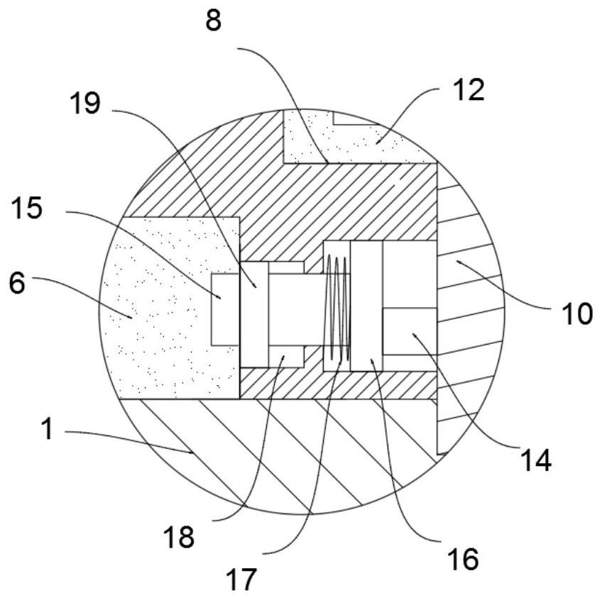
[0036] A fuel tank cover installation device, on the basis of the first embodiment, the second fixing mechanism includes a hidden groove 18 disposed on the tank cover plate 3 and located on one side of the installation cavity 9, and a rectangular card is movably inserted into the hidden groove 18. Block 15, one end of the rectangular clamping block 15 is clamped with the second fixing block 6, the other end of the rectangular clamping block 15 is fixed with a contact plate 16 located in the installation cavity 9, and the lower end of the threaded rod 10 is fixed with a contact plate 16. The touch block 14 and the rectangular block 15 are provided with a first elastic member.

[0037] It should be noted that the first elastic member includes a first spring 17 sleeved on the rectangular block 15 and located in the installation cavity 9 . The shape of the touch panel 16 is arc-shaped, and the second fixing block 6 is provided with a rectangular hole matching the size of the recta...


PUM


Abstract

The invention discloses an oil tank cover mounting device which comprises a first fixing block and a second fixing block which are fixed on the tank wall of an oil tank, the first fixing block and the second fixing block are arranged on the two sides of an oil filling hole respectively, and a tank cover plate covering the outer side of the oil filling hole is rotationally mounted on the first fixing block through a rotating shaft. A plugging block plugged in the oil filling hole is fixed to the bottom of the box cover plate, a rubber sealing layer is fixed to the outer side of the plugging block, a first fixing mechanism and a second fixing mechanism are arranged at the end, away from the first fixing block, of the box cover plate, and the first fixing mechanism comprises a rectangular clamping groove and a mounting cavity which are formed in the end, away from the first fixing block, of the box cover plate; and the rectangular clamping groove communicates with the interior of the mounting cavity. Through the arrangement of the clamping sleeve, the rectangular block, the operation block, the threaded rod, the second fixing block and the rectangular clamping block, the whole mounting device can be used for mounting the box cover plate, double fixation is achieved after mounting, the fixing effect is good, and fixing is firm.

Description

technical field [0001] The invention relates to the field of installation of fuel tank accessories, in particular to a fuel tank cover installation device. Background technique [0002] Automobile fuel tank is the full name of automobile fuel tank. At present, with the development of the automobile industry and the revitalization of the domestic automobile industry, the demand for automobile fuel tanks by major automobile manufacturers is showing an obvious growth trend. Automobile fuel tanks are divided into materials; iron fuel tanks and aluminum alloy fuel tanks. With the application and development of various new materials, the rust prevention of iron fuel tanks has become the biggest problem of fuel tank quality. Especially in today's focus on environmental protection work. In terms of heavy trucks: In the process of promoting the National 45 vehicles, the problem that affects the promotion of new models is the quality of my country's oil, of which the key is the qual...

Claims


Application Information

Patent Timeline
Patent Type & Authority Applications(China)
IPC IPC(8): B60K15/04
CPCB60K15/0406B60K2015/0458B60K2015/0451
Inventor 杨结海雷章军蒋超龙童声超
Owner WUHU TYCO AUTOMOTIVE TECH CO LTD
Why Eureka
Try Eureka