
Diode cutting and feeding device

A diode and cutting mechanism technology, applied in the field of diode cutting and feeding devices, can solve the problems of wrong direction of diodes, low efficiency of manual placement, etc., and achieve the effect of solving production efficiency problems

Pending Publication Date: 2022-07-29
SUZHOU XTONG PHOTOVOLTAIC TECH CO LTD
View PDF0 Cites 0 Cited by
  • Summary
  • Abstract
  • Description
  • Claims
  • Application Information

AI Technical Summary

Problems solved by technology

[0002] In the production of photovoltaic modules, the diodes are usually cut and installed manually. The efficiency of manual placement is low, and there is a certain probability of placing the diodes in the wrong direction.

Method used


Image

  • Diode cutting and feeding device
  • Diode cutting and feeding device
  • Diode cutting and feeding device

Examples


Embodiment Construction

[0018] Hereinafter, terms used in the specification will be briefly described, and the embodiments will be described in detail. All terms used herein, including descriptive terms or technical terms, should be construed as having the meanings understood by those of ordinary skill in the art. However, these terms may have different meanings according to the intentions of those of ordinary skill in the art, precedents, or the emergence of new technologies.

[0019] Also, some terms may be selected by the applicant, and in this case, the meanings of the selected terms will be described in detail in the detailed description of the embodiments. Therefore, the terms used herein must be defined based on the meanings of the terms together with the descriptions throughout the specification. Furthermore, when a component "comprises" or "comprises" an element, unless there is a specific description to the contrary, the component may also include other elements, but not exclude other elem...


PUM


Abstract

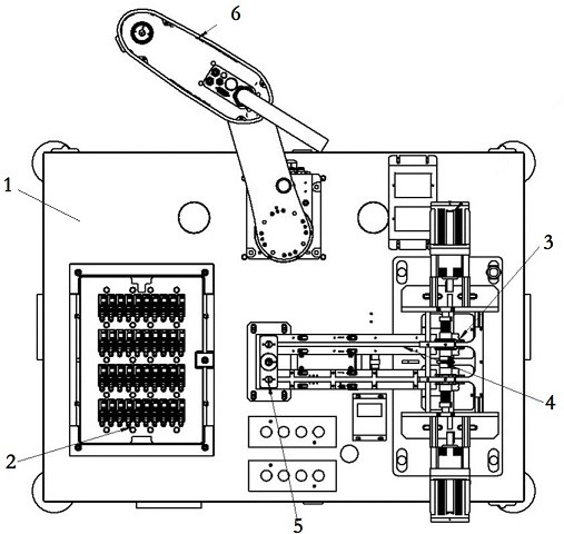
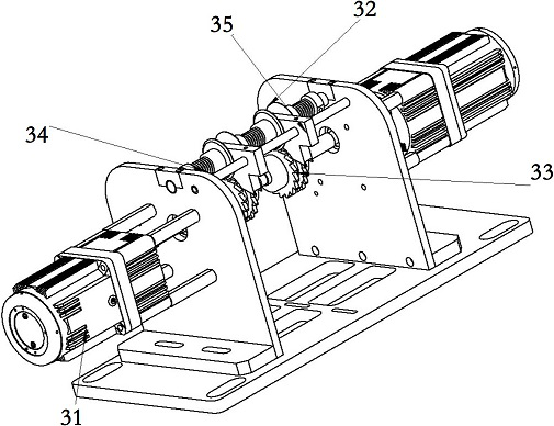
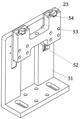
A diode cutting and feeding device comprises a base (1), a positioning tray (2) arranged on one side of the base (1), a cutting mechanism (3) arranged on the other side of the base (1), a diode track (4) arranged below the cutting mechanism (3) and a material receiving mechanism (5) arranged at the tail end of the diode track (4). A diode (23) is cut off by the cutting mechanism (3) and then conveyed to the material receiving mechanism (5) along the diode track (4), a plurality of positioning holes (21) are formed in the positioning tray (2), copper sheet workpieces (22) are arranged in the positioning holes (21), a manipulator (6) is further arranged on the base (1), and the manipulator (6) is connected with the cutting mechanism (3). And the manipulator (6) is used for moving the diode (23) on the material receiving mechanism (5) and positioning the diode (23) on the corresponding copper sheet workpiece (22). According to the invention, through gear transmission, diodes are kept consistent after being cut off, the flexible action of the four-axis manipulator is matched, the structural design and control are combined by utilizing the mechanical structure principle, and the problem of production efficiency is solved.

Description

technical field [0001] The invention relates to a diode cutting and feeding device. Background technique [0002] In the production of photovoltaic modules, the diodes are usually cut off and installed manually. The efficiency of manual placement is low, and there is a certain probability that the diodes are placed in the wrong direction. SUMMARY OF THE INVENTION [0003] In order to overcome the efficiency problem encountered in the production process of the prior art, the purpose of the invention of this product is to provide a diode cutting and feeding device with high production efficiency. [0004] In order to achieve the above purpose, the present invention provides a diode cutting and feeding device, comprising a base, a positioning tray arranged on one side of the base, a cutting mechanism arranged on the other side of the base, The diode track arranged below the cutting mechanism and the material receiving mechanism arranged at the end of the diode track, the cut...

Claims


Application Information

Patent Timeline
IPC IPC(8): B65G47/91B65G47/74H01L21/67H02S40/34H01L31/18
CPCB65G47/91B65G47/74H01L21/67092H02S40/34H01L31/18
Inventor 周民任艳秋刘当超张伟
Owner SUZHOU XTONG PHOTOVOLTAIC TECH CO LTD
Learn More