Multifunctional bridge erecting machine and bridge erecting construction method

A bridge erecting machine, multi-functional technology, applied in the direction of erecting/assembling bridges, bridges, bridge construction, etc., can solve the problems of inconvenient counterweight and affecting construction efficiency, and achieve the effect of small space occupation and high efficiency

Pending Publication Date: 2022-07-29
河南宏远智能起重机有限公司
View PDF1 Cites 1 Cited by
  • Summary
  • Abstract
  • Description
  • Claims
  • Application Information

AI Technical Summary

Problems solved by technology

[0005] The present invention aims to provide a multifunctional bridge erecting machine to solve the technical problems of inconvenient counterweight and affecting construction efficiency in the prior art

Method used


Image

  • Multifunctional bridge erecting machine and bridge erecting construction method
  • Multifunctional bridge erecting machine and bridge erecting construction method
  • Multifunctional bridge erecting machine and bridge erecting construction method

Examples


Embodiment 1

[0054] A multifunctional bridge erecting machine, see Figure 1 to Figure 10 .

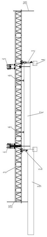
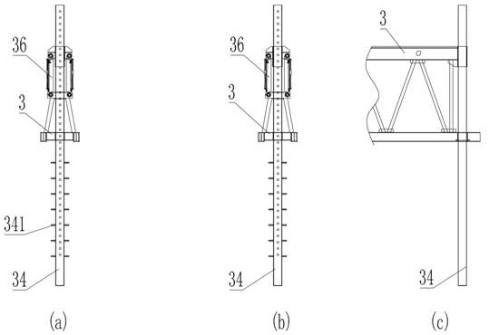
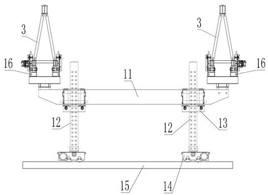
[0055] like figure 1 As shown, the multifunctional bridge erecting machine includes a front support device 1 and a rear support device 2. The bottom of the front support device 1 and the rear support device 2 are respectively provided with a walking mechanism that can move left and right on the track. The front support device and the rear support device Two longitudinal main load-bearing beams 3 are arranged at the upper interval, and two front and rear lifting cranes 4 are arranged on the main load-bearing beams 3 . The front support device 1 and the rear support device 2 play the role of supporting the main load-bearing beam 3, and the front support device 1 and the rear support device 2 can drive the main load-bearing beam 3 to move left and right, that is, move laterally; figure 2 As shown, from the end-side perspective, the main load-bearing beam 3 is in the shape of a triangle as a whole,...

Embodiment 2

[0074] The embodiment of the present invention also provides a bridge erection construction method, the construction method adopts the multifunctional bridge erection machine in Embodiment 1, and specifically includes the following steps:

[0075] (1) The bridge erection machine is arranged in place:

[0076] (1.1) Combination figure 1 As shown, transverse rails are arranged on the built bridge pier 4 and on the bridge built section 5, and the track is arranged in a position so that the bridge erection machine can hoist and move the prefabricated beam 7 on the corresponding bridge pier by the lifting crane 4.

[0077] (1.2) Set the front support device 1 and the rear support device 2 on the corresponding rails.

[0078] When the bridge erection machine is initially arranged, the front support device 1 and the rear support device 2 are installed by means of a crane.

[0079] (1.3) Fix the two main load-bearing beams 3 on both sides of the top of the front support device 1 and t...


PUM


Abstract

The invention belongs to the technical field of bridge construction, and particularly relates to a multifunctional bridge erecting machine and a bridge erecting construction method.The multifunctional bridge erecting machine is characterized in that two longitudinal main spandrel girders are arranged on a front supporting device and a rear supporting device, and a front lifting crown block and a rear lifting crown block are arranged on the main spandrel girders; side fixed lifting trolleys are respectively arranged at two ends of a transverse bearing beam of the lifting crown block; the movable lifting trolleys are arranged on the section, located between the two main bearing beams, of the transverse bearing beam, and due to the fact that the three lifting trolleys are arranged on the lifting crown block, the bridge girder erection machine can lift middle prefabricated beams and side prefabricated beams, and the multifunctional bridge girder erection machine has a self-balancing function and is convenient to use. The situation that the bridging efficiency is affected due to the fact that counterweight needs to be carried out when the lateral precast beam is hoisted is avoided; in the hoisting process of the side precast beam, the multifunctional bridge girder erection machine does not need to be moved to the space outside the side edge of a bridge, so that the multifunctional bridge girder erection machine can be used for bridging under the working condition of narrow space of existing lines such as expressways and urban rails, and normal traffic operation cannot be influenced.

Description

technical field [0001] The invention belongs to the technical field of bridge construction, and particularly relates to a multifunctional bridge erection machine and a bridge erection construction method. Background technique [0002] With the continuous development of social infrastructure, there are more and more lines for elevated construction or widening construction on existing lines. According to traditional construction methods, when these lines are constructed, truck cranes or crawler cranes are required to install prefabricated beams. , In the process of hoisting the prefabricated beam frame, the car crane or crawler crane needs to carry out closed construction on the existing line, which has a great impact on the operation of the urban line, and the construction of the car crane or crawler hanger has higher requirements on the road surface, and the existing line There may be cable pipes, or national defense cables, or water pipes, or gas pipes, etc. These pipes hav...

Claims


Application Information

Patent Timeline
Patent Type & Authority Applications(China)
IPC IPC(8): E01D21/00B66C11/04B66C13/08B66C5/02
CPCE01D21/00B66C11/04B66C5/02B66C13/08
Inventor 韩国杰韩新广何雨龙陈永久孙海丽
Owner 河南宏远智能起重机有限公司
Why Eureka
Try Eureka