Supercharge Your Innovation With Domain-Expert AI Agents!

Socket type disc buckle type formwork horizontal supporting device and working method

A horizontally supported and socket-type technology, which is applied in the field preparation of formwork/formwork/work frame, construction components, construction, etc., can solve the problems of poor economy, lower bearing capacity of vertical poles, and large elongation of vertical poles, etc. problem, to achieve good economy and improve the bearing capacity of the bracket

Pending Publication Date: 2022-07-29
SOUTHEAST UNIV
View PDF0 Cites 0 Cited by
  • Summary
  • Abstract
  • Description
  • Claims
  • Application Information

AI Technical Summary

Problems solved by technology

[0004] The technical problem to be solved by the present invention is to provide a horizontal support device and working method for a socket-type disc buckle formwork against the above-mentioned deficiencies in the prior art. The extension length of the pole at the top of the frame is too large, which reduces the bearing capacity of the pole, resulting in dense spacing between the poles, increasing the workload of installation and dismantling, and poor economic efficiency. The horizontal support device can fully exert the bearing capacity of the pole , to transmit the load axis of the horizontal formwork to the vertical rod, and at the same time, the horizontal support structure acts as a two-way horizontal rod at the top of the bracket, so that there is no stretching length at the top of the bracket, thereby greatly improving the bearing capacity of the bracket and achieving better economy

Method used


Image

  • Socket type disc buckle type formwork horizontal supporting device and working method
  • Socket type disc buckle type formwork horizontal supporting device and working method
  • Socket type disc buckle type formwork horizontal supporting device and working method

Examples


Embodiment Construction

[0034] The present invention will be described in further detail below with reference to the accompanying drawings and specific preferred embodiments.

[0035] In the description of the present invention, it should be understood that the orientation or positional relationship indicated by the terms "left side", "right side", "upper", "lower part", etc. are based on the orientation or positional relationship shown in the drawings, only For the convenience of describing the present invention and simplifying the description, rather than indicating or implying that the referred device or element must have a particular orientation, be constructed and operate in a particular orientation, "first", "second", etc. importance, and therefore should not be construed as a limitation to the present invention. The specific dimensions used in this embodiment are only for illustrating the technical solution, and do not limit the protection scope of the present invention.

[0036] The present ...


PUM


Abstract

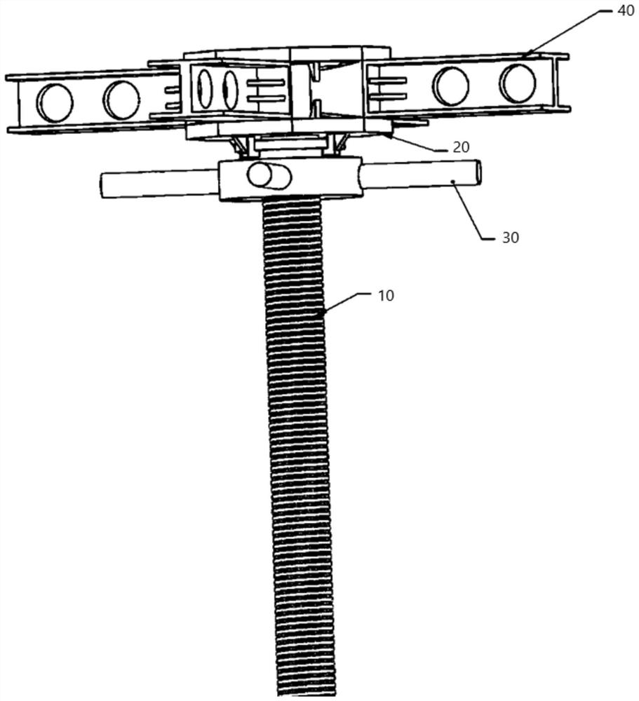
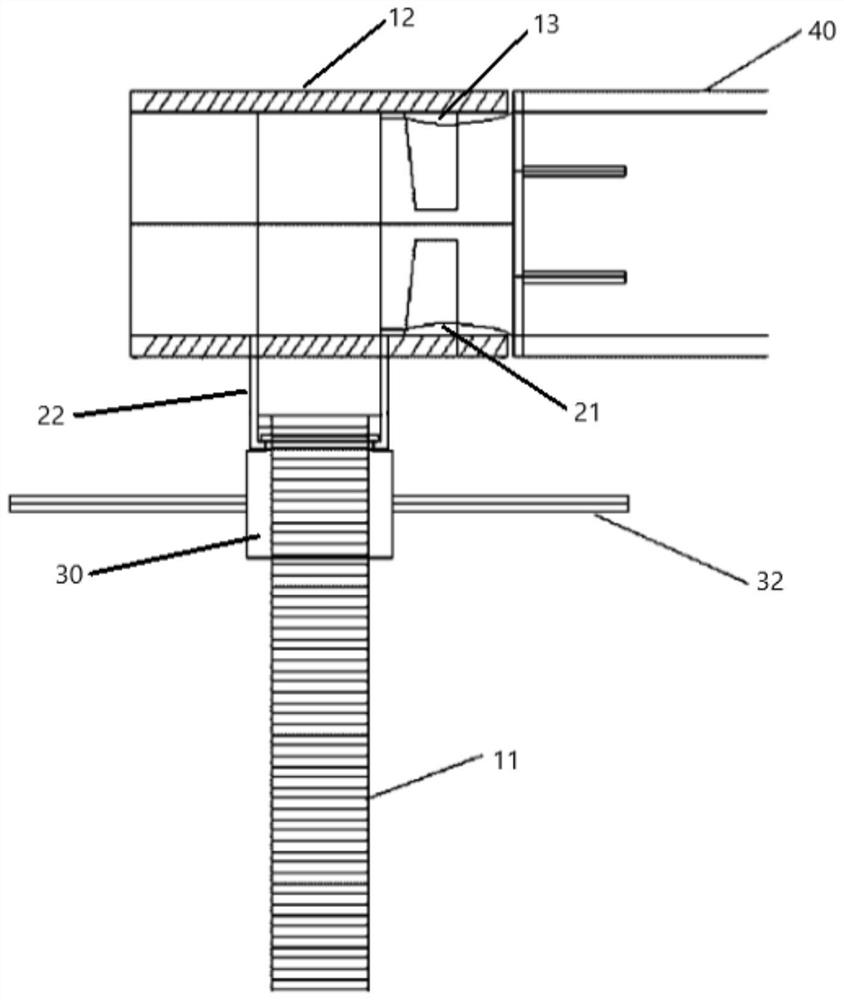
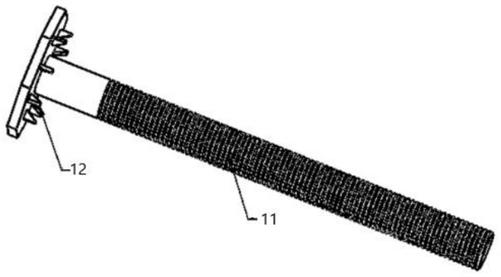
The invention discloses a horizontal supporting device for a socket type disc buckle type formwork and a working method. The supporting device comprises a disc buckle vertical rod, a plane supporting disc, a spiral disc and a cross beam rod. The disc buckle vertical rod comprises a screw rod and a disc surface, and a plurality of first bolts are distributed on the disc surface; a second bolt is arranged on one side surface of the plane support disc, and a buckle is arranged on the other side surface; a plane supporting disc through hole is formed in the center of the plane supporting disc; the spiral disc is formed by stacking three concentric discs with different diameters, and the spiral disc is clamped by the buckles of the plane supporting disc; the center of the spiral disc is provided with a spiral disc through hole and is provided with internal threads, and a screw rod of the disc buckle vertical rod penetrates through the spiral disc through hole and is in threaded fit with the spiral disc through hole; the end of the cross beam rod is a trapezoid body, and slotted holes are formed in the two opposite trapezoid faces of the trapezoid body respectively and used for the first plug pin and the second plug pin to be inserted in. According to the horizontal supporting device, the bearing capacity of the vertical rod can be brought into full play, the load axis of the horizontal formwork is transmitted to the vertical rod, the bearing capacity of the support is greatly improved, and good economical efficiency is achieved.

Description

technical field [0001] The invention relates to the technical field of a socket-type disc buckle type formwork support frame, in particular to a socket type disc buckle type formwork horizontal support device and a working method. Background technique [0002] The support frame is a variety of supports erected by workers on the construction site to solve problems such as vertical and horizontal transportation, formwork support, and safety protection. It is an important temporary structure in the construction process. The support frame can be divided into a fastener type support frame, a bowl buckle type support frame, a door type support frame, and a socket type disc buckle type support frame according to different erection methods. Among them, the socket-type buckle-type support frame has been favored by engineers and technicians more and more in recent years due to its unique advantages such as high bearing capacity, time-saving and labor-saving, fast and convenient constr...

Claims


Application Information

Patent Timeline
IPC IPC(8): E04G11/52
CPCE04G11/52
Inventor 武雷巫嘉鑫
Owner SOUTHEAST UNIV
Features
  • R&D
  • Intellectual Property
  • Life Sciences
  • Materials
  • Tech Scout
  • Unparalleled Data Quality
  • Higher Quality Content
  • 60% Fewer Hallucinations
Learn More