Roller device of auxiliary stress mechanism

A technology of rollers and mounting holes, which is applied in the direction of engine lubrication, slitting machinery, mechanical equipment, etc., can solve problems such as wear of sliding shoes and walking wheels, and complex working conditions on site, so as to avoid friction and wear, reduce wear, and prolong The effect of service life

Pending Publication Date: 2022-07-29
SHANGHAI TIANDI MINING EQUIP TECH CO LTD +2
View PDF0 Cites 0 Cited by
  • Summary
  • Abstract
  • Description
  • Claims
  • Application Information

AI Technical Summary

Problems solved by technology

[0004] However, due to the complexity of the on-site working conditions, no matter which of the above-mentioned improvement schemes can completely avoid the influence of rock

Method used


Image

  • Roller device of auxiliary stress mechanism
  • Roller device of auxiliary stress mechanism
  • Roller device of auxiliary stress mechanism

Examples


Example Embodiment

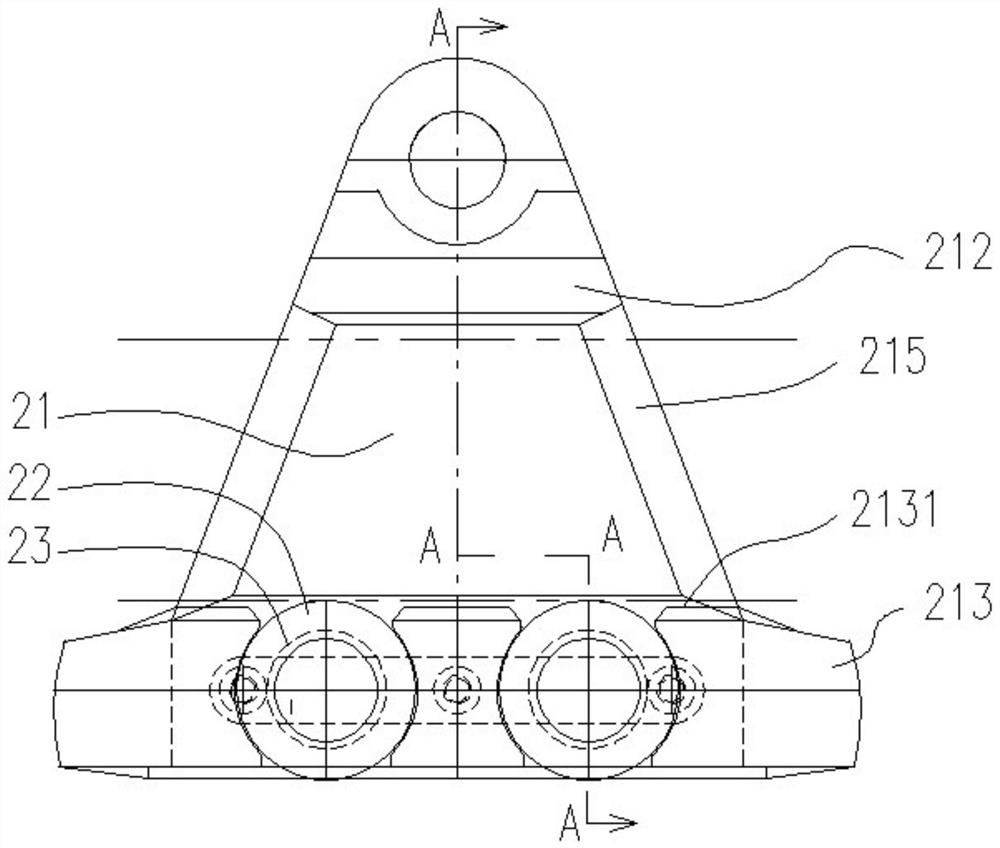
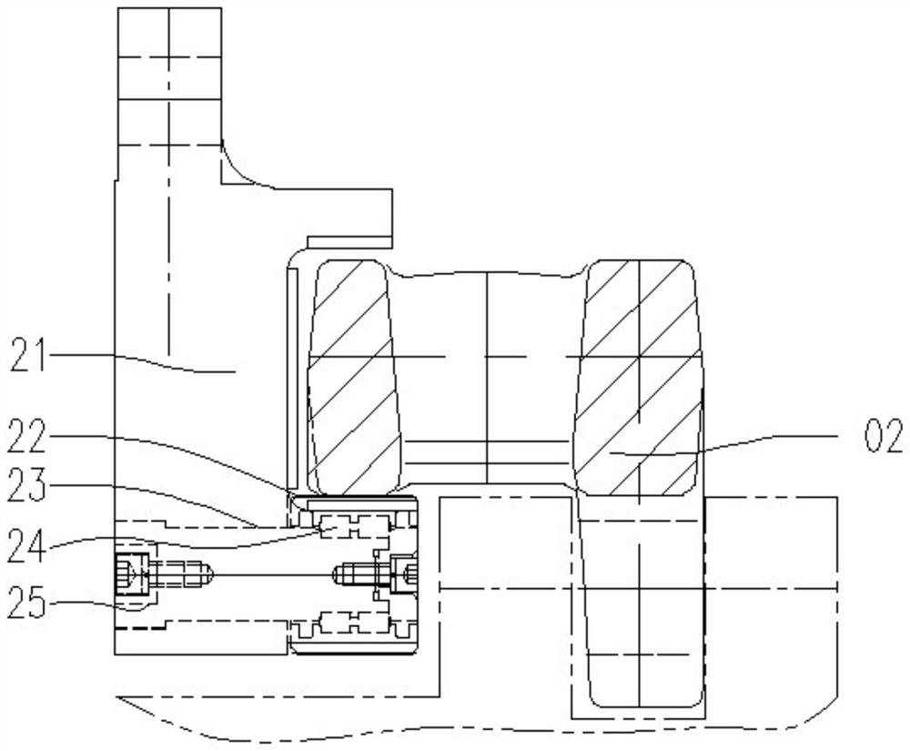
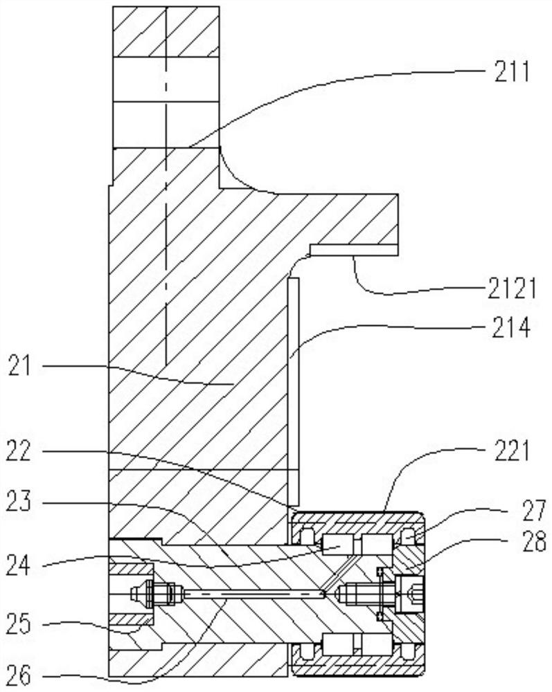
[0028] like Figure 1-3 As shown, the present invention discloses a roller device (which can be referred to as a roller device for short) of an auxiliary force-bearing mechanism, comprising a vertical plate 21 and a roller 22, the upper part of the vertical plate is provided with a connecting hole 211 that runs through the front and rear, the vertical plate A rearwardly protruding upper beam body 212 is provided on the upper middle and upper portion of the rear side panel surface of the panel and below the connecting hole, and a rearwardly protruding guide body 213 is provided on the lower portion of the rear side panel surface of the vertical panel. Both the upper beam body and the guide body are in the shape of strips extending left and right. The guide body is provided with a plurality of left and right spaced roller mounting holes, the axis of the roller mounting holes extends horizontally front and rear, and the top and bottom of the roller mounting holes are respectively...


PUM


Abstract

The roller device of the auxiliary stress mechanism comprises a vertical plate and a roller, a front-back through connecting hole is formed in the upper portion of the vertical plate, an upper beam body protruding backwards is arranged on the upper middle portion of the rear side plate face of the vertical plate and below the connecting hole, and a guide body protruding backwards is arranged on the lower portion of the rear side plate face of the vertical plate. A plurality of roller mounting holes are formed in the guide body, the axes of the roller mounting holes horizontally extend front and back, the top and the bottom of each roller mounting hole are respectively provided with a top notch and a bottom notch which are through front and back, one roller is arranged in each roller mounting hole, the rollers are mounted on the vertical plate, and gaps are kept between the rollers and the roller mounting holes; the highest point of the idler wheel is higher than the top face of the guiding body, and the upper beam body, the idler wheel and the vertical plate part located between the upper beam body and the guiding body define a three-face surrounding structure with a backward opening. The device is used in an auxiliary stress mechanism, and is used for applying constant downward thrust to a walking system, so that the walking mechanism is always kept in a normal meshing state, and effective traction force is provided.

Description

technical field [0001] The invention relates to a roller device, which is mainly used on an auxiliary force-bearing mechanism used in conjunction with the track of a shearer traveling system. The auxiliary force-bearing mechanism can provide a constant downward force for the traveling system, so that the traveling mechanism can always maintain In the normal meshing state, the roller device is the part of the auxiliary force bearing mechanism that is in direct contact with the track. Background technique [0002] When the shearer guide shoe encounters a large amount of hard and difficult-to-break block rock environment, the walking system is easy to fail prematurely, especially the hardened layer of the guide shoe bottom hook wears rapidly, and the guide frame of the guide shoe wears too much. The normal meshing between the traveling wheel and the pin row cannot be guaranteed, which will eventually lead to a greatly weakened climbing ability of the shearer, which will serious...

Claims


Application Information

Patent Timeline
IPC IPC(8): E21C29/22F16N21/00
CPCE21C29/22F16N21/00
Inventor 胡滔章立强郭岱王振乾胡璟董超顾恩洋魏升刘振高振帮全保朝
Owner SHANGHAI TIANDI MINING EQUIP TECH CO LTD
Why Eureka
Try Eureka