Industrial steam intelligent control electric butterfly valve

An electric butterfly valve, steam technology, applied in the direction of valve lift, valve details, valve device, etc., can solve the problems of large seal wear, low valve stability, low seal quality, etc., to ensure seal quality, reduce wear, reduce Effects of seal wear

Pending Publication Date: 2022-07-29
JIANGSU YUANYANG VALVE INTELLIGENT CONTROL CO LTD
View PDF0 Cites 0 Cited by
  • Summary
  • Abstract
  • Description
  • Claims
  • Application Information

AI Technical Summary

Problems solved by technology

[0003] In order to solve the problems of large seal wear, low follow-up seal quality, and low stability of the overall use of the valve in the use of the general industrial steam electric butterfly valve mentioned above, the above can effectively reduce seal wear and ensure the follow-up seal quality, effectively improving To ensure the stability of the overall use of the valve, the present invention is realized through the following technical solutions: an electric butterfly valve intelligently controlled by industrial steam, including a valve body, an electromagnetic coil is embedded in the inner wall of the valve, and the inner wall of the valve is fixed A sealing mechanism is installed, the sealing mechanism includes a valve seat, the inner wall of the valve seat is fixedly connected with a rubber ring, the outer periphery of the rubber ring is fixedly sleeved with a metal soft ring, and the left end of the valve seat is slidingly inserted with a magnetic ring. The rear end of the valve body is movably connected with an adjustment mechanism, the adjustment mechanism includes a worm, the periphery of the worm is fixedly connected with an electric block, the left end of the electric block is slidingly plugged with a contact rod, and the inner wall of the electric block is elastically connected with an electric shock head A hinge rod is movably connected between the electric contact head and the inner wall of the electric block, a groove ring is sleeved on the periphery of the worm screw, and an electric coupling ring sleeved on the worm screw is fixedly connected to the rear end of the valve body.

Method used


Image

  • Industrial steam intelligent control electric butterfly valve
  • Industrial steam intelligent control electric butterfly valve
  • Industrial steam intelligent control electric butterfly valve

Examples


Embodiment Construction

[0018] The technical solutions in the embodiments of the present invention will be clearly and completely described below with reference to the accompanying drawings in the embodiments of the present invention. Obviously, the described embodiments are only a part of the embodiments of the present invention, but not all of the embodiments. Based on the embodiments of the present invention, all other embodiments obtained by those of ordinary skill in the art without creative efforts shall fall within the protection scope of the present invention.

[0019] The example of the electric butterfly valve intelligently controlled by industrial steam is as follows:

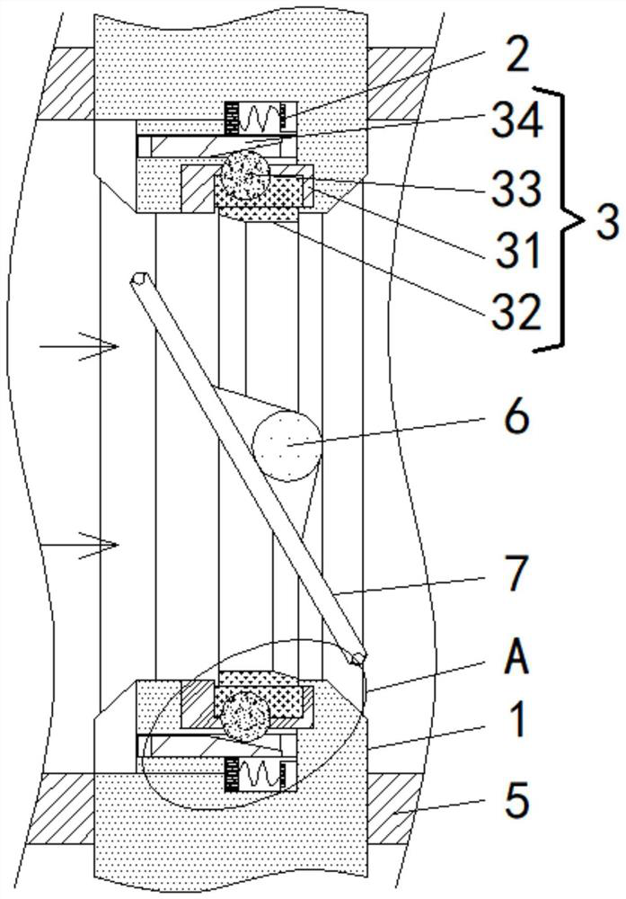
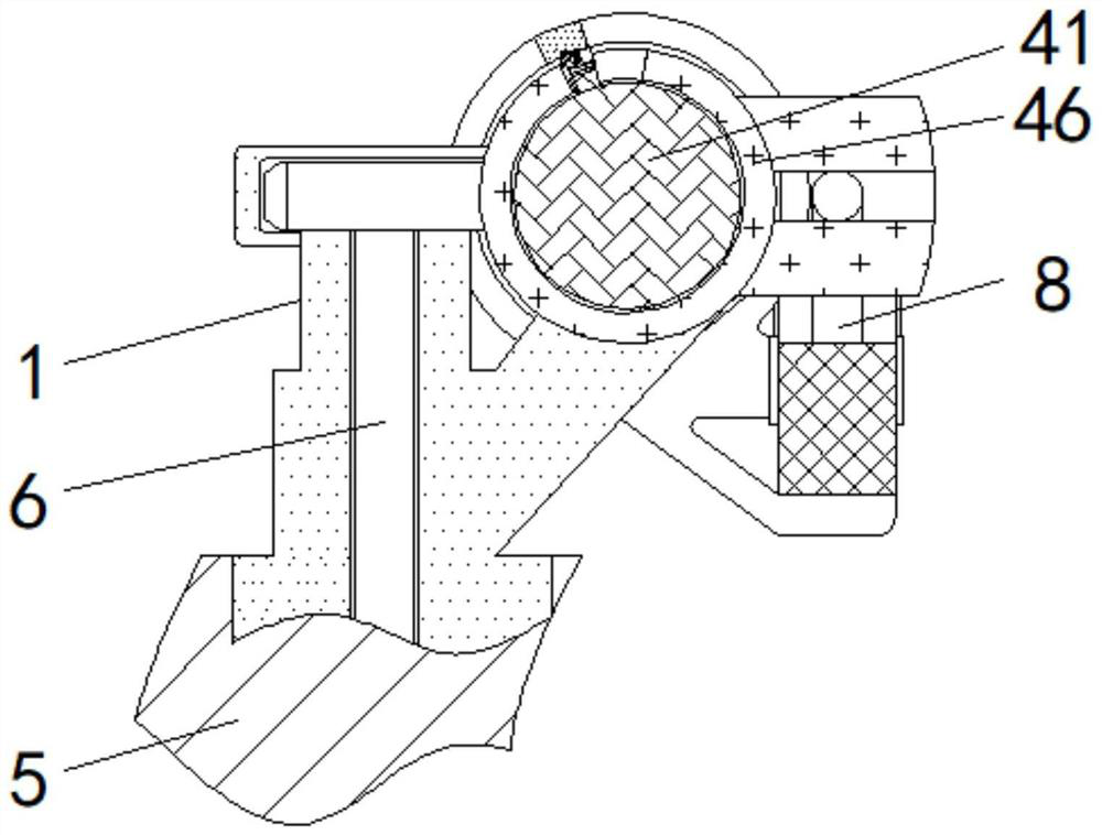
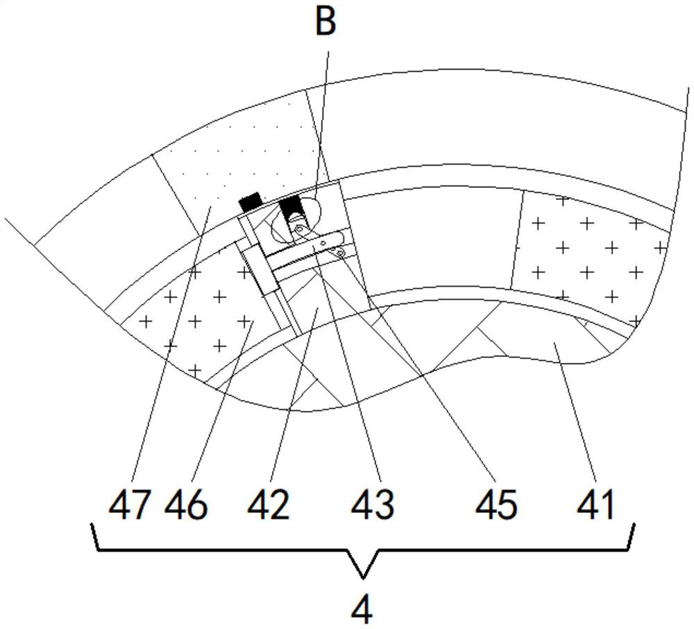
[0020] see Figure 1-Figure 5 , an electric butterfly valve for intelligent control of industrial steam, comprising a valve body 1, an electromagnetic ring 2 is embedded in the inner wall of the valve body 1, a sealing mechanism 3 is fixedly installed on the inner wall of the valve body 1, and the sealing mechanism 3 includ...


PUM


Abstract

The invention relates to the technical field of butterfly valves, and discloses an industrial steam intelligent control electric butterfly valve which comprises a valve body, an electromagnetic ring is embedded in the inner wall of the valve body, a sealing mechanism is fixedly installed on the inner wall of the valve body and comprises a valve seat, and a rubber ring is fixedly connected to the inner wall of the valve seat. The periphery of the rubber ring is fixedly sleeved with a metal soft ring, the left end of the valve seat is slidably connected with a magnetic ring in an inserted mode, the rear end of the valve body is movably connected with an adjusting mechanism, the adjusting mechanism comprises a worm, and the periphery of the worm is fixedly connected with an electric block. According to the industrial steam intelligent control electric butterfly valve, when the valve plate is closed, high pressure on the steam side is used for automatically providing high extrusion force between the rubber ring and the valve plate, and when the valve plate is opened, the rubber ring is controlled in advance to automatically reduce the extrusion force; therefore, the sealing abrasion is effectively reduced, the subsequent sealing quality is ensured, and the overall use stability of the valve is effectively improved.

Description

technical field [0001] The invention relates to the technical field of butterfly valves, in particular to an electric butterfly valve with intelligent control of industrial steam. Background technique [0002] Existing electric butterfly valves for industrial steam always install the sealing ring on the valve seat during use. When the valve plate is closed, it can be fully squeezed with the sealing ring to achieve the effect of filling the connection gap. However, when the valve plate is closed, its edge will preferentially squeeze with the edge of the sealing ring, which will lead to The tangential hard extrusion deformation occurs, and when the valve plate is opened, the sealing ring will be hard extruded again, which will lead to serious wear of the sealing ring in the long run, greatly affecting its service life, and the sealing ring is fully Compression will cause the problem of large opening and closing torque, which is not conducive to the stability of the overall us...

Claims


Application Information

Patent Timeline
Patent Type & Authority Applications(China)
IPC IPC(8): F16K1/22F16K31/06F16K31/53
CPCF16K1/2266F16K1/221F16K31/0675F16K31/0655F16K31/535
Inventor 玉金贵陈英镇杨支援
Owner JIANGSU YUANYANG VALVE INTELLIGENT CONTROL CO LTD
Why Eureka
Try Eureka