High-precision direction finding method under large-step beam scanning condition

A high-precision direction-finding and beam-scanning technology, which is applied in direction-determining orientators, radio wave measurement systems, measuring devices, etc., can solve the problem of difficulty in balancing direction-finding accuracy and system response speed, increasing data processing difficulty, and occupying a large system Resources and other issues, to achieve both processing speed and direction-finding accuracy, reduce resource overhead, and high direction-finding accuracy

Pending Publication Date: 2022-07-29
NO 54 INST OF CHINA ELECTRONICS SCI & TECH GRP
View PDF0 Cites 0 Cited by
  • Summary
  • Abstract
  • Description
  • Claims
  • Application Information

AI Technical Summary

Problems solved by technology

[0002] In traditional beamforming technology, the direction finding accuracy is usually related to the beam width of the array and the angle scanning step. The narrower the beam width and the smaller the angle search step, the higher the direction finding accuracy, and at the same time, the data processing difficulty of the system is also higher. Therefore, in the conventional beamforming technology, it is difficult to balance the direction finding accuracy and the system response speed; in the traditional sum-difference beam angle measurement method, it is often necessary to calculate the angle discrimination value first and compare it with the locally saved angle discrimination curve, etc. The data is fitted to obtain the deviation angle between the source azimuth and the beam pointing angle, and then the direction of arrival of the signal source is calculated from the deviation angle and beam pointing angle. Therefore, the storage of local data and subsequent fitting calculations will take up a lot of system resources , and the source azimuth is calculated indirectly by the deviation angle, which is more likely to introduce errors

Method used


Image

  • High-precision direction finding method under large-step beam scanning condition
  • High-precision direction finding method under large-step beam scanning condition
  • High-precision direction finding method under large-step beam scanning condition

Examples


Embodiment Construction

[0031] The present invention will be further described in detail below in conjunction with the accompanying drawings.

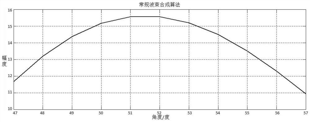
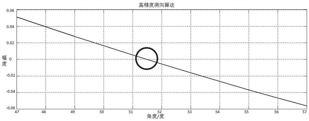
[0032] A high-precision direction finding method under the condition of large stepping beam scanning, refer to figure 1 , through the weighted control of the array, the synthetic beam is scanned in the airspace to obtain a preliminary estimate of the source azimuth angle, and the center of the beam is pointed to the rough measurement direction, and the array is divided into two symmetrical sub-arrays to sum the beams. , difference calculation, using the amplitude and phase relationship between the sum and difference beams to accurately estimate the source azimuth angle.

[0033] The process of the method mainly includes: after both sub-arrays point to the rough angle measurement, calculate the amplitude value of the Fourier transform of the data received by the composite array, and find the sampled data corresponding to the maximum amplitude value. At the sa...


PUM


Abstract

The invention provides a high-precision direction finding method under a large-step beam scanning condition, and belongs to the technical field of array signal processing. According to the method, firstly, information source azimuth coarse measurement is performed through conventional beam forming airspace scanning, and then the information source azimuth angle is accurately calculated by using the amplitude and phase relation of sum and difference beams between subarrays, so that high-precision direction finding under the condition of large-step beam scanning is realized.

Description

technical field [0001] The invention relates to the technical field of array signal processing, in particular to a high-precision direction finding method under the condition of large stepping beam scanning. Background technique [0002] In the traditional beamforming technology, the direction finding accuracy is usually related to the beam width of the array and the angle scanning step. The narrower the beam width and the smaller the angle search step, the higher the direction finding accuracy. Therefore, in the conventional beamforming technology, it is difficult to take into account the direction finding accuracy and the system response speed; in the traditional sum-difference beam angle measurement method, it is often necessary to first calculate the angle detection value and compare it with the locally saved angle detection curve, etc. The data is fitted to obtain the deviation angle between the source azimuth and the beam pointing angle, and then the incoming wave dire...

Claims


Application Information

Patent Timeline
Patent Type & Authority Applications(China)
IPC IPC(8): G01S3/00
CPCG01S3/00
Inventor 苗峻窦修全李晋陈建宇边疆
Owner NO 54 INST OF CHINA ELECTRONICS SCI & TECH GRP
Why Eureka
Try Eureka