Reid vapor pressure estimation method and device, electronic equipment and storage medium
A vapor pressure and Reid technology, which is applied in the petrochemical field, can solve the problems of result error and complex vapor pressure estimation method of Reid, and achieve the effect of simple calculation process and small error.
- Summary
- Abstract
- Description
- Claims
- Application Information
AI Technical Summary
Benefits of technology
Problems solved by technology
Method used
Image

Examples
Embodiment 1
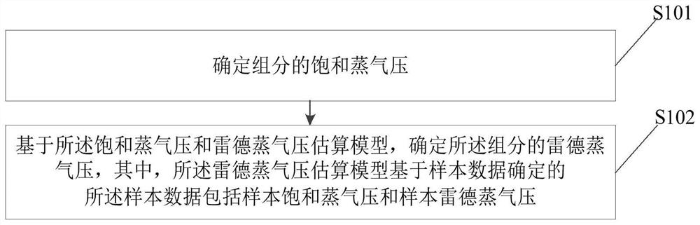
[0055] The embodiment of the present application provides a method for estimating Reid vapor pressure, figure 1 A schematic diagram of the realization flow of the method for estimating the Reid vapor pressure provided in the embodiment of the present application, such as figure 1 shown, including:
[0056] Step S101, determining the saturated vapor pressure of the component.
[0057] In the examples of the present application, the components may be pure components or petroleum fractions. The determination of the saturated vapor pressure of the component may directly measure the saturated vapor pressure of the component through a measuring device, and the measuring device sends the measured saturated vapor pressure to the electronic device, so that the electronic device determines the saturated vapor pressure of the component.
[0058] In some embodiments, when the saturated vapor pressure cannot be directly measured, the critical parameter of the component can be obtained; t...
Embodiment 2
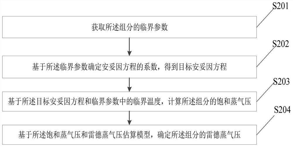
[0065] Based on the foregoing embodiments, the embodiments of the present application further provide a method for estimating Reid vapor pressure, figure 2 A schematic diagram of the implementation flow of another method for estimating Reid vapor pressure provided in the embodiment of the present application, such as figure 2 shown, including:
[0066] Step S201, obtaining critical parameters of the components.
[0067] In the embodiment of the present application, the critical parameter may be directly measured and / or obtained by calculation. In the embodiment of the present application, the critical parameter may include: critical temperature, boiling point, critical pressure, eccentricity factor, and the like.
[0068] Step S202 , determining the coefficient of the Artoine equation based on the critical parameter to obtain the target Artoine equation.
[0069] In the embodiment of the present application, when the component is a pure component, the coefficient of the An...
Embodiment 3
[0084] Based on the foregoing embodiments, embodiments of the present application further provide a method for estimating Reid vapor pressure, including:
[0085] Step S301, acquiring sample data.
[0086] In the embodiment of the present application, the sample data includes the sample saturated vapor pressure and the sample Reid vapor pressure. Sample saturated vapor pressure and sample Reid vapor pressure were analyzed based on historical data.
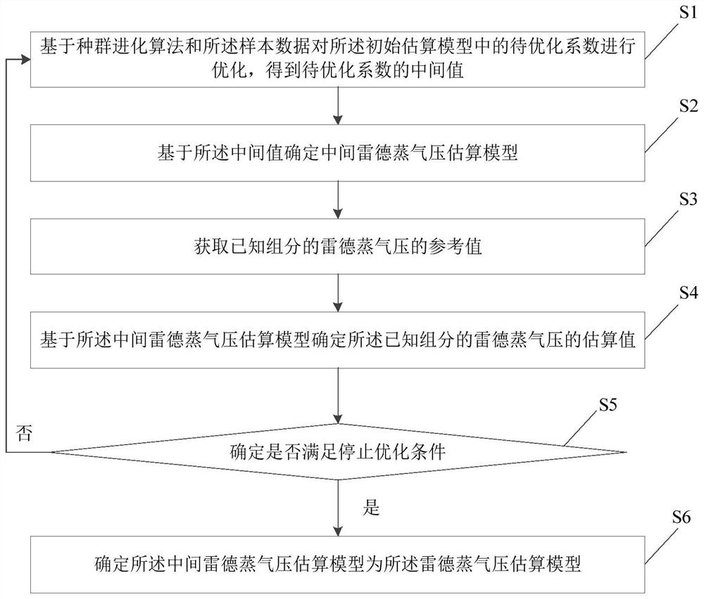
[0087] Step S302, an initial estimation model is trained based on the sample data to obtain the Reid vapor pressure estimation model.
[0088] In the embodiment of the present application, the initial estimation module is a neural network model, and the training of the initial estimation model based on sample data may be regression training based on a swarm evolution algorithm. The swarm evolution algorithm may be a standard differential evolution algorithm, a quasi-Newton method, or the like.
[0089] In the examples of this ap...
PUM
 Abstract
Description
Claims
Application Information
PatSnap Eureka turns technology decisions into work you can execute. Powered by our Innovation Knowledge Graph, it runs expert workflows across engineering, life sciences, materials and intellectual property. Get your review-ready output in minutes.


