Charging protection device of new energy automobile

A new energy vehicle, charging protection technology, applied to charging stations, coupling devices, electric vehicles, etc., can solve the problems of burned vehicles, fault expansion, high charging current, etc., to improve protection capabilities, prolong service life, and avoid floating charging status Effect

Pending Publication Date: 2022-07-29
RIZHAO POLYTECHNIC
View PDF6 Cites 0 Cited by
  • Summary
  • Abstract
  • Description
  • Claims
  • Application Information

AI Technical Summary

Problems solved by technology

At present, most new energy vehicles use DC charging piles for fast charging, but due to the high output power of DC charging piles, especially in the initial stage of car battery charging, the charging current is relatively high.
However, in the prior art, the effect on power protection during the charging process of the vehicle is limited, and there is no mechanical protection mechanism, which makes it difficult to protect the battery pack and charging pile when the power fails.
[0003] At present, the charging gun head basically does not have a direct and effective contact active separation mechanism. When a fault occurs during the charging process, it is easy to cause further expansion of the fault, or even burn the entire vehicle.
Publication numbers: CN208782162U and CN109217024A, the patent name is a DC charging pile with charging protection function; Publication number: CN109217023A and CN208782163U, the patent name is a DC charging pile with fault removal function; Publication number: CN201811117676.3 and CN208813002U , the name of the patent is a DC charging pile with automatic tripping protection for the charging interface; the above-mentioned patent discloses the structure of the charging interface of the new energy vehicle, or the contacts are separated by elastic force, the separation of the contacts is short and the separation is not complete

Method used


Image

  • Charging protection device of new energy automobile
  • Charging protection device of new energy automobile
  • Charging protection device of new energy automobile

Examples


Embodiment Construction

[0033] The present invention will be further described in detail below with reference to the accompanying drawings, so that those skilled in the art can refer to the description and implement accordingly.

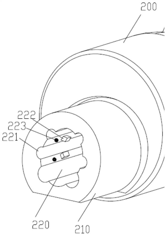
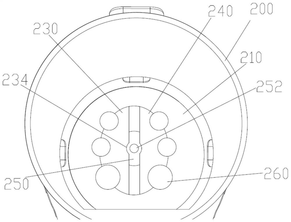
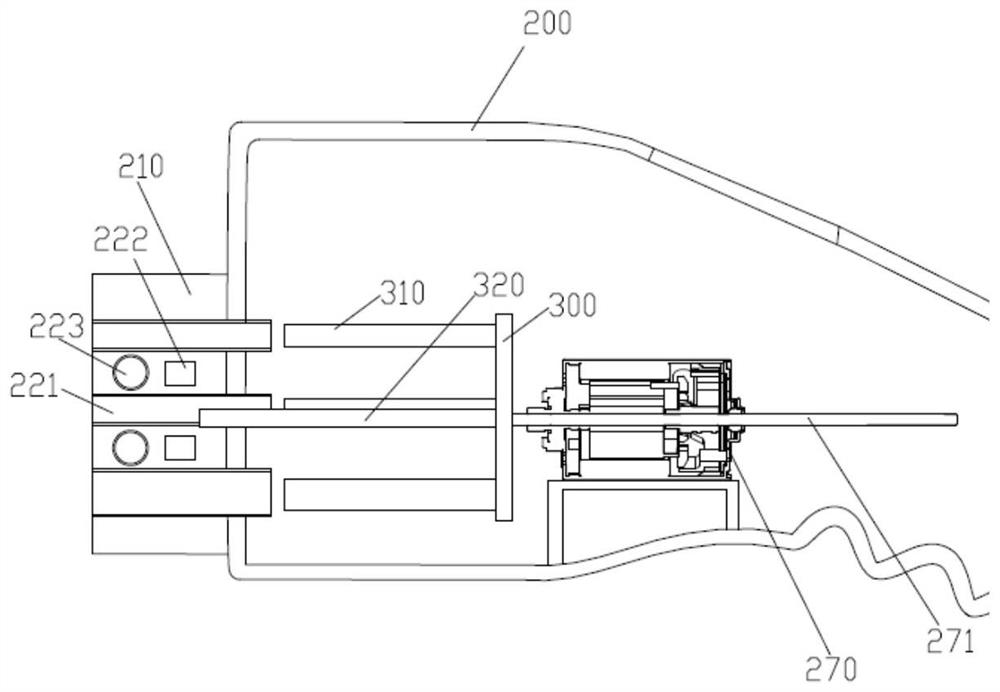
[0034] like Figure 1-13 As shown, the present invention provides a charging protection device for a new energy vehicle. Specifically, a cylindrical plug terminal 210 is protruded from the charging gun head 200, and the plug terminal 210 is plugged into the charging pin of the vehicle. On the interface, the connection between the battery pack and the charging pile is realized to charge the battery pack. The charging protection device is arranged on the charging gun head 200 of the charging pile, and plays a protective role in the charging process of the battery pack.

[0035] A plurality of first grooves 221 are distributed on the outer circumference of the first through hole 220 , at least one guide block 222 is protruded from the side walls of the first through hole 220 ...


PUM


Abstract

The invention discloses a charging protection device of a new energy automobile, a charging gun head is provided with a plugging end, the plugging end is provided with a first through hole in a penetrating manner, the first through hole is internally provided with a pair of half-section bodies in a radial telescoping manner, and the charging gun head is internally provided with a telescoping mechanism; the telescoping mechanism controls the radial telescoping process of the half-section body in the first through hole, the telescoping end of the telescoping mechanism is provided with an ejector pin disc, and the axial outer side end of the ejector pin disc is provided with ejector pins in one-to-one correspondence with conductive plugging holes of the charging gun head. The length of the ejector pin is not smaller than that of the conductive plug hole, and the ejector pin is arranged in the conductive plug hole in a telescopic mode. According to the invention, the protection capability of the new energy automobile in the charging process is improved.

Description

technical field [0001] The invention relates to the technical field of new energy vehicles, in particular to a charging protection device for new energy vehicles. Background technique [0002] The pressure of global energy consumption and air pollution is becoming more and more prominent, and new energy vehicles are gradually being promoted and applied, and new energy vehicles, especially pure electric vehicles, need to be charged through charging piles to provide energy. At present, most of the new energy vehicles use DC charging piles for fast charging, but due to the large output power of DC charging piles, especially in the initial stage of vehicle battery charging, the charging current is relatively high. However, in the prior art, the protection of power consumption during vehicle charging is limited, and no mechanical protection mechanism is provided, which makes it difficult to protect the battery pack and the charging pile when the power consumption fails. [0003]...

Claims


Application Information

Patent Timeline
Patent Type & Authority Applications(China)
IPC IPC(8): H01R13/633B60L53/16
CPCH01R13/633B60L53/16
Inventor 刘成好夏鲁宁
Owner RIZHAO POLYTECHNIC
Why Eureka
Try Eureka