Wire inlet and outlet cabinet capable of bunching wires

A wire cabinet and wire harness technology, applied in busbar/line layout, electrical components, substation/power distribution device shell, etc., can solve problems such as difficult later maintenance and damage to the wire harness surface, and achieve easy maintenance, simple operation, and easy use Effect

Pending Publication Date: 2022-07-29
深圳市超业电力科技有限公司
View PDF1 Cites 0 Cited by
  • Summary
  • Abstract
  • Description
  • Claims
  • Application Information

AI Technical Summary

Problems solved by technology

[0006] The present invention provides an incoming and outgoing wire cabinet capable of harnessing wires, which has the beneficial effects of facilitating the arrangement of the wire harnesses and the protection of the wire harnesses, and solves the problem that the traditional binding method mentioned in the above background technology will cause damage to the surface of the wire harnesses. Problems that are more difficult to carry out post-repair

Method used


Image

  • Wire inlet and outlet cabinet capable of bunching wires
  • Wire inlet and outlet cabinet capable of bunching wires
  • Wire inlet and outlet cabinet capable of bunching wires

Examples


Embodiment 1

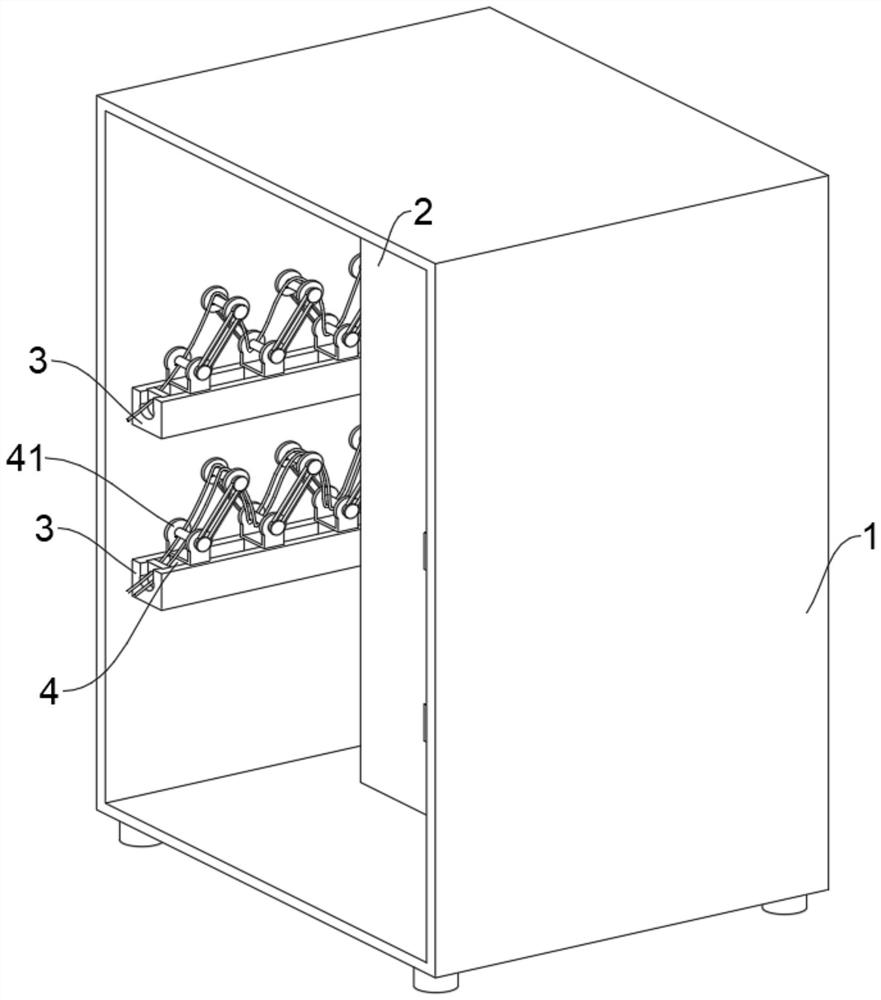
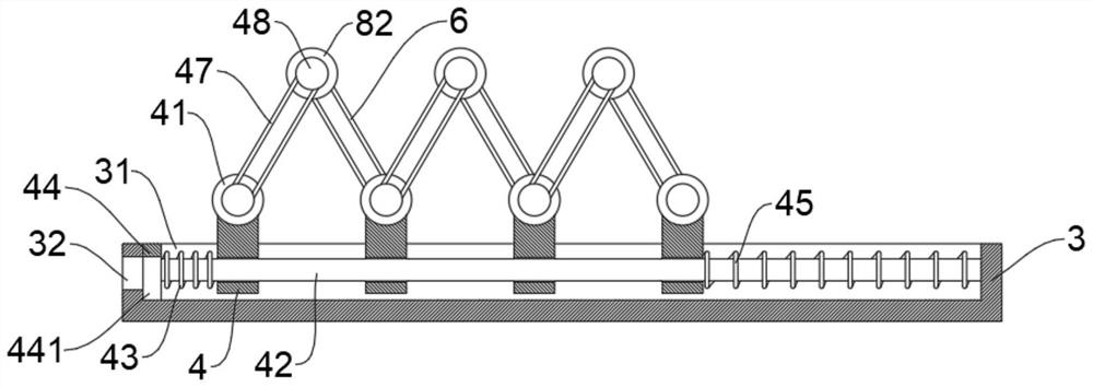
[0032] This embodiment is intended to facilitate solving the problem of how to organize the wiring harness, please refer to Figure 1-4 , the present embodiment discloses an incoming and outgoing wire cabinet that can bundle wires, including an incoming and outgoing wire cabinet body 1 and an electrical component 2 installed in the incoming and outgoing wire cabinet body 1, and a holder 3 is installed on the inner wall of the incoming and outgoing wire cabinet body 1, A chute 31 is provided on the retainer 3, and a harness slider 4 is slidably installed in the chute 31. The harness slider 4 slides in the chute 31, and a first bearing seat 41 is slidably installed on the harness slider 4. The first bearing A first wire roller shaft 7 is installed on the seat 41, a first protruding block 46 is connected to the outer side of the middle of the first bearing seat 41, and a first connecting rod 47 is sleeved on the first protruding block 46, and the first connecting rod 47 One end a...

Embodiment 2

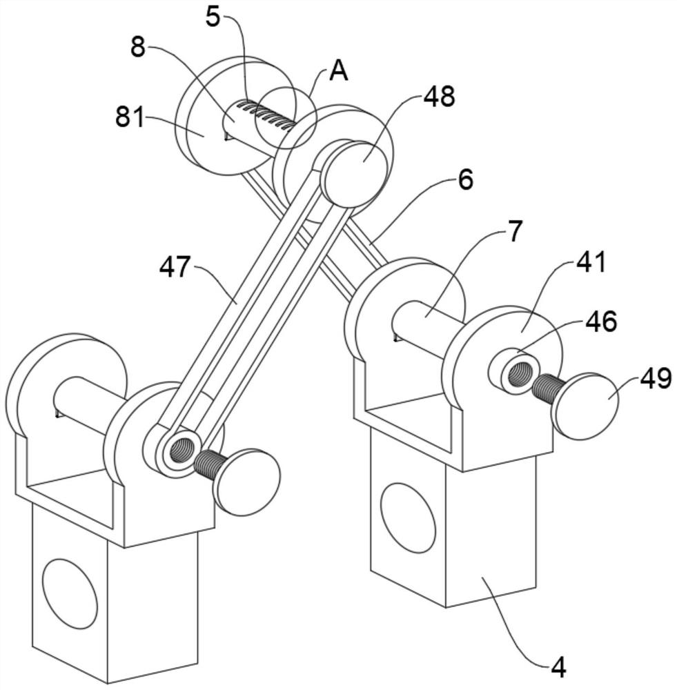
[0038] This embodiment is intended to facilitate solving the problem of how to install the wire harness on the first wire roller shaft 7. This embodiment is an improvement made on the basis of Embodiment 1. For details, please refer to Figure 2-4 , a rubber abutting block 411 is installed on the inner wall of the first bearing seat 41 , one end of the rubber abutting block 411 is connected to a limiting block 412 , and the limiting blocking block 412 and the rubber abutting block 411 are threadedly connected with the middle of the first bearing seat 41 Limit bar 49.

[0039] Under the action of the rubber abutting block 411 , both ends of the wire harness can abut against the rubber abutting block 411 , which can protect the wire harness.

[0040] By installing the limiting rod 49 , it is convenient to limit the first connecting rod 47 and the second connecting rod 6 to prevent them from sliding out of the outer side of the first protruding block 46 , and the protection effec...

Embodiment 3

[0047] This embodiment is intended to facilitate solving the problem of how to organize multiple wire harnesses. This embodiment is an improvement made on the basis of Embodiment 2. For details, please refer to figure 2 , image 3 and Figure 5 , a limit slot 5 is set on the second wire roller 8, and the wire harness of the electrical component 2 is inserted into the limit slot 5.

[0048] Multiple wire harnesses can be respectively clamped in the limiting slot 5, so that the wire harnesses can be fixed in a regular and orderly manner without being cluttered.

[0049] A U-shaped wire outlet slot 32 is opened on the side wall of the holder 3 , and the U-shaped wire outlet slot 32 is matched with the chute 31 .

[0050] After the installation of the multiple wire harnesses is completed, they are finally uniformly extended from the U-shaped wire outlet slot 32, which is convenient for arranging the multiple wire harnesses of the wire harness so that they will not be loosened f...


PUM


Abstract

The invention relates to the technical field of incoming and outgoing line cabinets, and discloses an incoming and outgoing line cabinet capable of bunching, the incoming and outgoing line cabinet comprises an incoming and outgoing line cabinet body and an electric appliance element installed in the incoming and outgoing line cabinet body, a holder is installed on the inner wall of the incoming and outgoing line cabinet body, a sliding groove is formed in the holder, a wiring harness sliding block is slidably installed in the sliding groove, and the wiring harness sliding block is installed in the wiring harness sliding block. A first bearing seat is slidably installed on the wire harness sliding block, a first wire guide roller shaft is installed on the first bearing seat, a first protruding block is connected to the outer side of the middle of the first bearing seat and sleeved with a first connecting rod, and the end, away from the first protruding block, of the first connecting rod is sleeved with a second protruding block; the wire harnesses are integrally installed between the first wire guide roller shafts and the second wire guide roller shafts in a Z shape, the arrangement range of the wire harnesses is enlarged, the peripheries of the first wire guide roller shafts and the second wire guide roller shafts are all round, the radian is large, and the wire harnesses cannot be damaged.

Description

technical field [0001] The invention relates to the technical field of cable entry and exit cabinets, in particular to an entry and exit cable cabinet capable of wire harnessing. Background technique [0002] High-voltage incoming and outgoing line cabinets are used for on-off, control or protection in the power generation, transmission, distribution, power conversion and consumption of the power system. Various places such as high-rise buildings in enterprises and residential quarters are electrical equipment that assembles some power protection devices such as switches and circuit breakers into one. [0003] Chinese invention patent CN201610001708 discloses a low-voltage incoming and outgoing line cabinet and low-voltage incoming and outgoing line equipment. It includes a cabinet body with an opening on the front side, the inside of the cabinet body is provided with an incoming and outgoing wire compartment partition plate that divides the inside of the cabinet body into ...

Claims


Application Information

Patent Timeline
Patent Type & Authority Applications(China)
IPC IPC(8): H02B1/20H02G3/04H02G3/02H02B1/30
CPCH02B1/202H02G3/04H02G3/02H02B1/30
Inventor 徐超银
Owner 深圳市超业电力科技有限公司
Why Eureka
Try Eureka