
Construction platform based on port channel pouring

A technology for construction platforms and port waterways, which is applied in infrastructure engineering, scaffolding accessories, construction, etc., can solve the problems of inconvenient concrete block cleaning, inconvenient use, and construction workers being easily affected by walking on the scaffolding.

Pending Publication Date: 2022-08-02
韦作仪
View PDF0 Cites 0 Cited by
  • Summary
  • Abstract
  • Description
  • Claims
  • Application Information

AI Technical Summary

Problems solved by technology

[0003] Existing scaffolds are equipped with ladders for construction workers to go up and down the scaffolds, but the angle of the ladders cannot be adjusted, making it inconvenient to use, and it is not convenient to clean up the fallen concrete blocks on the scaffolds, which makes the construction workers easily affected when walking on the scaffolds. To this end, we propose a construction platform based on port waterway perfusion

Method used


Image

  • Construction platform based on port channel pouring
  • Construction platform based on port channel pouring
  • Construction platform based on port channel pouring

Examples


Embodiment 1

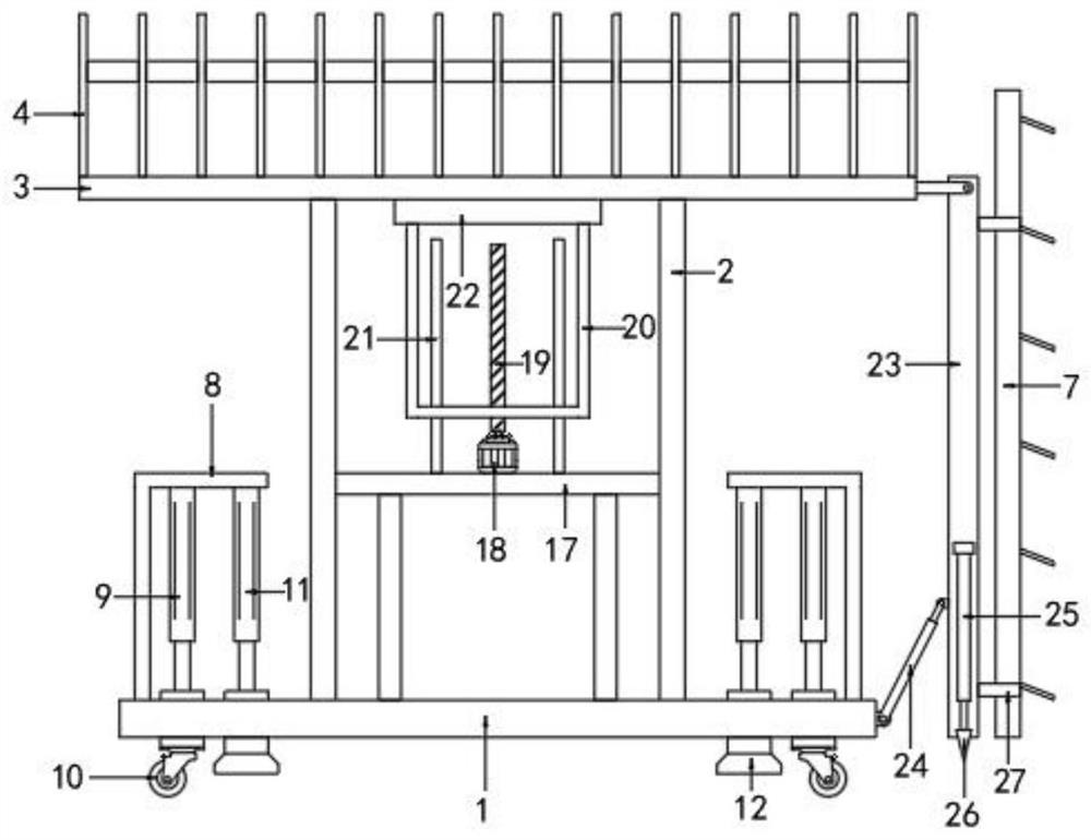
[0022] refer to Figures 1 to 5 , a construction platform based on port waterway perfusion, comprising, a fixed plate 1; a support rod 2 is provided on the top of the fixed board 1, and a top plate 3 is provided on the top of the early support rod 2; in order to protect the construction personnel, on the top of the top plate 3 The outer side is provided with a protective fence 4, and the protective fence 4 is installed on the right side to enter and exit through a hinge, which is convenient for construction personnel to enter and exit;

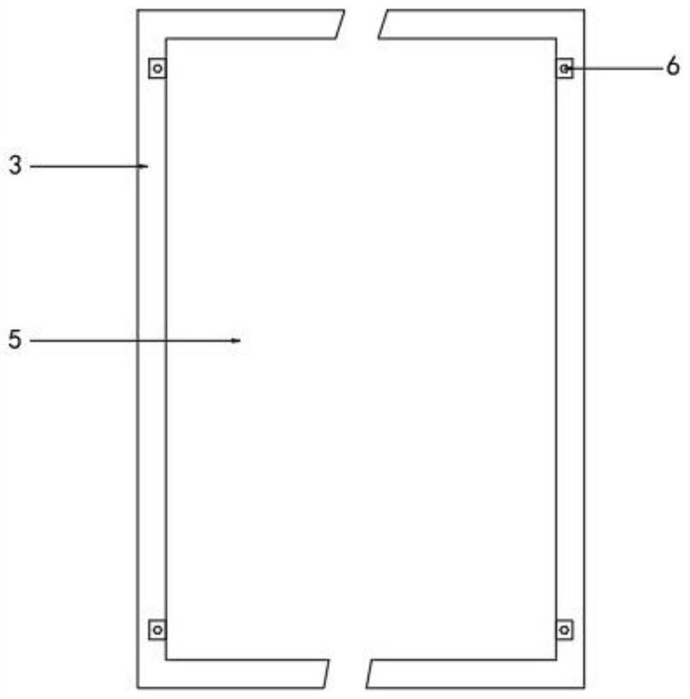
[0023] A groove is provided on the top of the top plate 3, and an iron plate 5 whose top is flush with the top plate 3 is attached and connected in the groove. There are fixing bolts 6 connected with the top plate 3 to fix the iron plate 5. When the concrete blocks on the iron plate 5 need to be cleaned, the iron plate 5 can be taken out upward by removing the fixing bolts 6; An angle adjustment device is arranged; a buffer device is arranged...

Embodiment 2

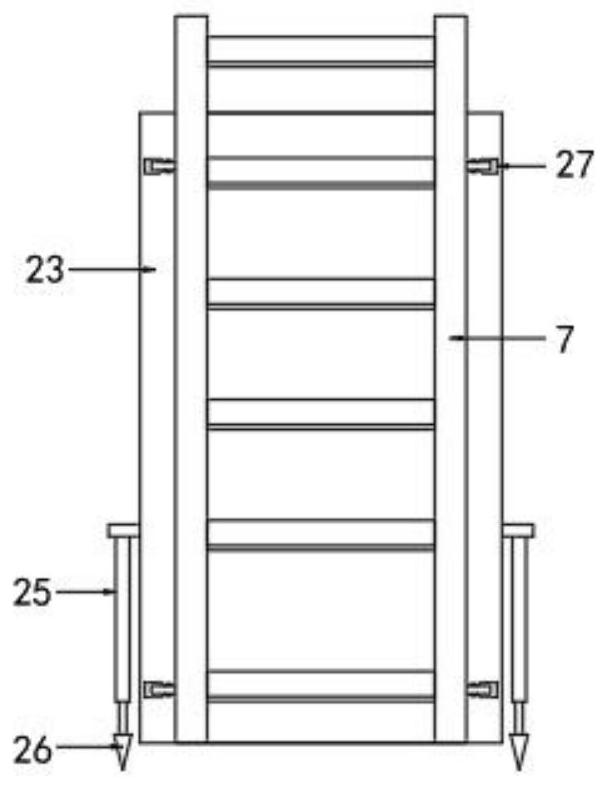
[0030] refer to Figure 1 to Figure 2 , the bottom ends of the front and rear sides of the mounting plate 23 are provided with electric push rods 25, and the output ends of the electric push rods 25 are provided with support rods 26 whose bottom ends are tapered. The support rod 26 can be driven to lean against the ground, so as to cooperate with the electric telescopic rod 24 and further play the role of supporting the ladder 7 .

[0031] The rest of the structure is the same as that of Example 1.

[0032]Using process: push the fixed plate 1 to the required position through the universal wheel 10, drive the support base 12 to contact the ground through the action cylinder 2 11, so that the fixed plate 1 can be placed flat on the uneven ground, and then drive the universal direction through the action cylinder 1 9 When the wheel 10 moves upward, it can be placed stably through the support base 12; when the construction worker needs to get on the iron plate 5, the electric te...


PUM


Abstract

The invention discloses a construction platform based on port channel pouring, and belongs to the technical field of port channel construction. A supporting rod is arranged at the top of the fixing plate, and a top plate is arranged at the top of the supporting rod; a protective fence is arranged on the outer side of the top of the top plate; a groove is formed in the top of the top plate, an iron plate with the top flush with the top plate is connected into the groove in an attached mode, and a fixing bolt connected with the top plate is arranged on the iron plate. An angle adjusting device is arranged on the fixing plate; when a constructor needs to climb on an iron plate, the electric telescopic rod drives the mounting plate to rotate, the ladder can be driven to incline, the electric push rod drives the supporting rod to obliquely abut against the ground after inclining, and the electric telescopic rod can be matched to further play a role in supporting the ladder; and a constructor can enter the iron plate through the ladder for construction.

Description

technical field [0001] The invention relates to the technical field of port channel construction, in particular to a construction platform based on port channel perfusion. Background technique [0002] In the process of port and waterway construction, the construction of bored piles is a very important construction link. When pouring concrete, the construction personnel need to stand on the construction platform and hold a cement gun for pouring, and the existing construction platform is mainly scaffolding. [0003] Existing scaffolds are equipped with ladders for construction workers to get up and down the scaffolding, but the angle of the ladder cannot be adjusted, which is inconvenient to use, and it is inconvenient to clean up the concrete blocks falling from the scaffolding, which causes the construction workers to be easily affected when walking on the scaffolding. To this end, we propose a construction platform based on port waterway perfusion. SUMMARY OF THE INVENT...

Claims


Application Information

Patent Timeline
IPC IPC(8): E02D5/34E02D15/00E04G1/24E04G5/00E04G5/02E04G5/10
CPCE02D5/34E02D15/00E04G1/24E04G5/00E04G5/02E04G5/10E04G2001/244Y02E10/20
Inventor 韦作仪
Owner 韦作仪
Features
  • Generate Ideas
  • Intellectual Property
  • Life Sciences
  • Materials
  • Tech Scout
  • Unparalleled Data Quality
  • Higher Quality Content
  • 60% Fewer Hallucinations
Learn More