
Side slope anchoring and shotcreting supporting structure

A technology for bolting and shotcrete support and slope, which is applied in the directions of infrastructure engineering, construction, excavation, etc., can solve the problems that the preset holes cannot be closely matched, the supporting structure cannot be given, and the slope support and traction are easy to adjust. , The effect of ensuring strength and increasing stability

Pending Publication Date: 2022-08-02
NORTH CHINA UNIV OF WATER RESOURCES & ELECTRIC POWER
View PDF0 Cites 1 Cited by
  • Summary
  • Abstract
  • Description
  • Claims
  • Application Information

AI Technical Summary

Problems solved by technology

[0003] When laying anchors, due to the inaccuracy of drilling, the anchors cannot be closely matched with the preset holes on the slope. As a result, when supporting, the traditional support structure cannot give the slope a structural level. support and traction, making the support less stable

Method used


Image

  • Side slope anchoring and shotcreting supporting structure
  • Side slope anchoring and shotcreting supporting structure
  • Side slope anchoring and shotcreting supporting structure

Examples


Embodiment

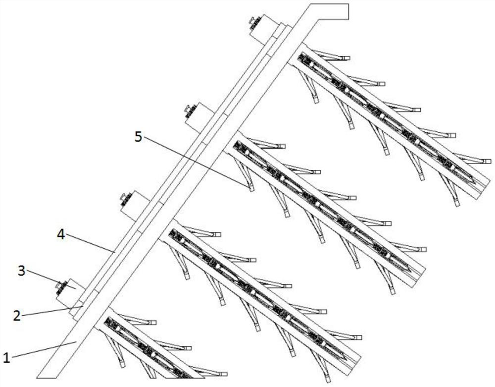
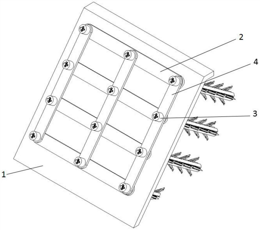
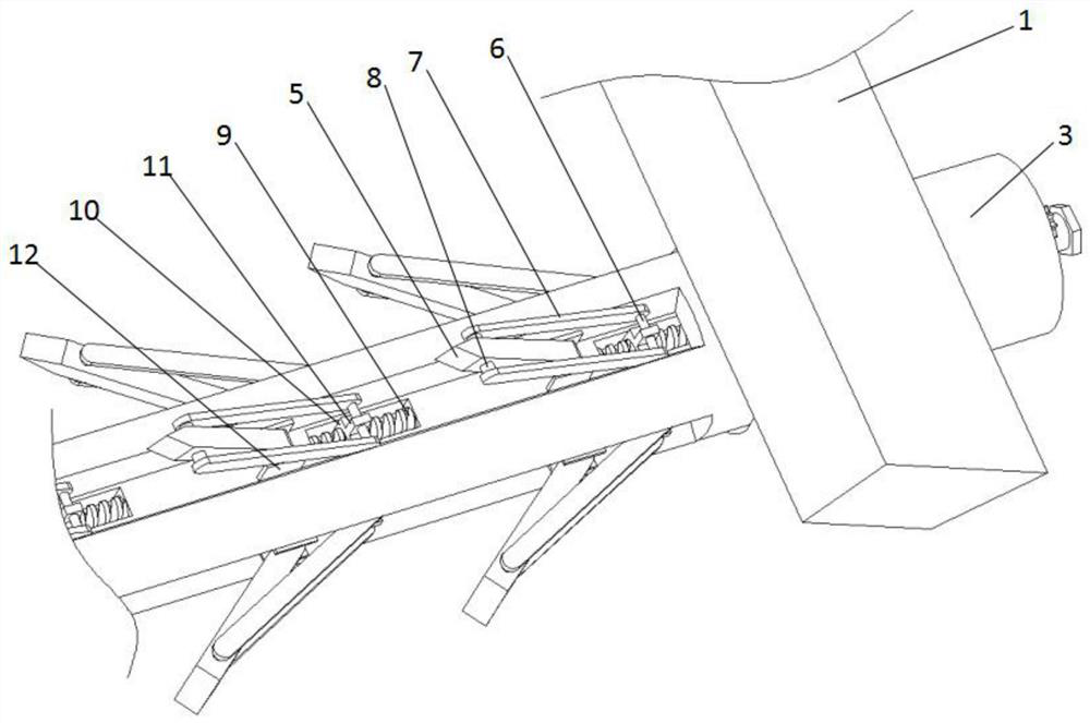
[0040] A kind of slope bolt and shotcrete support structure, such as Figure 1-4 As shown, it includes: a plurality of anchor rods 3, one end of which is respectively inserted into a plurality of arrays of through holes preset in the side slope 1; each anchor rod 3 is provided with a plurality of long grooves along the length direction, The grooves are evenly arranged along the circumferential direction of the anchor rod 3; a plurality of limit plates 5 are respectively rotated and erected in the plurality of elongated slots through the rotating assembly, and are evenly arranged along the longitudinal direction of the elongated slots. Specifically, as figure 2 and image 3 As shown in the figure, a square groove is formed at the bottom of each long groove; each set of rotating components includes: two shelf plates 12, both of which are fixedly arranged on the groove bottom of the long groove, and are located at one end of a corresponding square groove; A rotating shaft pass...


PUM


Abstract

The invention provides a side slope anchoring and shotcreting supporting structure which comprises a plurality of anchor rods, a plurality of supporting rods and a plurality of supporting rods. Each anchor rod is provided with a plurality of long-strip-shaped grooves in the length direction, and the long-strip-shaped grooves are evenly formed in the circumferential direction of the anchor rod. The multiple limiting plates are rotationally erected in the multiple long-strip-shaped grooves through rotating assemblies correspondingly and are evenly arranged in the length direction of the long-strip-shaped grooves; the multiple sets of driving assemblies are arranged in the multiple long-strip-shaped grooves correspondingly and synchronously drive the multiple sets of rotating assemblies in the same groove to rotate and expand outwards correspondingly, so that each limiting plate abuts against the hole wall of the corresponding through hole; the plurality of transverse fixing plates are fixedly connected with the plurality of anchor rods in the same row respectively; the longitudinal fixing plates are fixedly connected with the anchor rods in the same row, and a concrete spraying layer is arranged in a space formed by the longitudinal fixing plates and the transverse fixing plates. According to the device, the anchor rod and the preset drill hole can be tightly supported, the supporting structure and the slope are stably matched through traction and supporting, and the supporting strength is improved.

Description

technical field [0001] The invention relates to the technical field of bolt and shotcrete support, in particular to a side slope bolt and shotcrete support structure. Background technique [0002] The bolt and shotcrete support is composed of bolts and shotcrete panels. Its main function is to limit the free development of the surrounding rock deformation, adjust the stress distribution of the surrounding rock, and prevent the rock mass from falling loose. It can also be used as a temporary support during the construction process. It can also be used as a permanent support or lining in some cases. [0003] When laying the anchor rod, due to the inaccuracy of drilling, the anchor rod cannot be closely matched with the preset holes on the slope, resulting in the traditional support structure cannot give the slope a structural level during support. The support and traction are poor, making the support less stable. [0004] To this end, the present invention proposes a new slo...

Claims


Application Information

Patent Timeline
IPC IPC(8): E02D17/20E02D5/76E02D15/04
CPCE02D17/20E02D5/76E02D15/04Y02A10/23
Inventor 刘海宁段素真康鸣雷秦超
Owner NORTH CHINA UNIV OF WATER RESOURCES & ELECTRIC POWER
Learn More