
Composite reinforced high-fill slope structure

A technology for high filling slopes and slopes, which is applied in infrastructure engineering, excavation, separation methods, etc., can solve the problems of large land occupation, small comprehensive slope ratio, loose filling, etc., to save water resources, The effect of increasing the water storage capacity

Pending Publication Date: 2022-08-02
谢冬文
View PDF1 Cites 0 Cited by
  • Summary
  • Abstract
  • Description
  • Claims
  • Application Information

AI Technical Summary

Problems solved by technology

However, the slope ratio method has two problems in the application of high fill slopes: first, in order to ensure construction safety, the quality of mechanical compaction of the fill soil at the front edge of the slope is limited, and the fill soil is relatively loose, which may easily lead to shallow slope Landslides; second, the comprehensive slope ratio required for self-stabilization of high fill slopes is small, the slopes occupy a large area, and the amount of earth and rocks is large. On sites with steep original terrain, the slope may even become higher and higher and cannot converge
[0004] However, the existing compound-reinforced high-fill slope structure cannot actively avoid the problems of loose fill and slope collapse in the process of practical application, and at the same time, the gravel produced by slope collapse cannot effectively and it is easy to accumulate water on the slope protection, so the accumulated water cannot be effectively used

Method used


Image

  • Composite reinforced high-fill slope structure
  • Composite reinforced high-fill slope structure
  • Composite reinforced high-fill slope structure

Examples


Embodiment Construction

[0028] In order to make the technical means, creative features, achievement goals and effects realized by the present invention easy to understand, the present invention will be further described below with reference to the specific embodiments.

[0029] In the description of the present invention, it should be understood that the terms "upper", "lower", "front", "rear", "left", "right", "top", "bottom", "inside", " The orientation or positional relationship indicated by "outside" is based on the orientation or positional relationship shown in the accompanying drawings, and is only for the convenience of describing the present invention and simplifying the description, rather than indicating or implying that the indicated device or element must have a specific orientation, so as to The specific orientation structure and operation should not be construed as a limitation of the present invention; in the description of the present invention, it should be noted that, unless otherwi...


PUM


Abstract

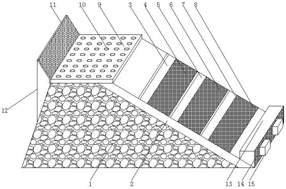
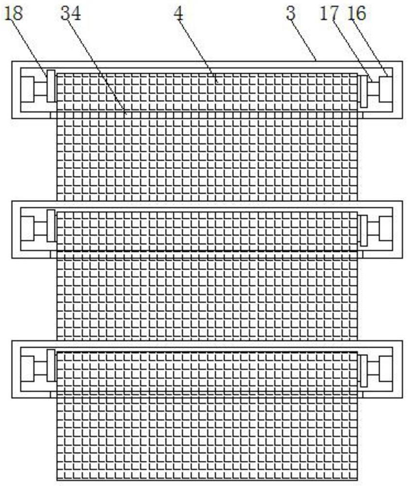
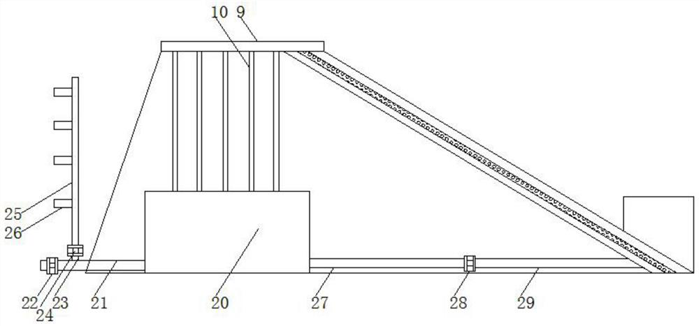
The invention relates to the technical field of side slopes, and discloses a composite reinforced high-fill side slope structure which comprises a side slope body, and a soil retaining protection mechanism, a water diversion mechanism and a smashing mechanism are arranged in the side slope body; the soil retaining protection mechanism comprises a soil layer, a first fixing shell, a second fixing shell, a third fixing shell, a first protection net, a second protection net, a third protection net, a fixing block, a fixing rod, a torsion spring and an inserting rod. A soil layer is arranged on the right side of the slope body. The torsion springs and the protective nets are arranged in the three fixing shells, the protective nets in the three fixing shells can be unfolded to cover the surface of a soil layer, after the fixing shells are fixed, a gravel layer on the top of the soil layer can be shielded through the unfolded protective nets and the fixing shells, and therefore the soil layer can be protected; the problems that broken stones fall off and soil is loose are actively solved, and the protection nets among the three fixed shells are unfolded, so that the protection device can be suitable for protection slopes of different sizes.

Description

technical field [0001] The invention relates to the technical field of side slopes, in particular to a composite reinforced high fill side slope structure. Background technique [0002] In engineering practice, the supporting methods used for fill slopes mainly include: gravity retaining wall, buttress retaining wall, pile-plate retaining wall and slope method. Among them, the height of gravity retaining wall, buttress retaining wall and pile plate retaining wall should not exceed 10m, 10m and 15m respectively. Therefore, the available treatment methods for high fill slopes with a height of more than 40m are relatively limited, and the current technical standard recommends that the slope rate method be preferred. However, the slope rate method has two problems in the application of high fill slopes: First, in order to ensure construction safety, the mechanical compaction quality of the fill at the front edge of the slope is limited, and the fill is relatively loose, which e...

Claims


Application Information

Patent Timeline
Patent Type & Authority Applications(China)
IPC IPC(8): E02D17/20B01D47/06E03F5/10B02C4/08
CPCE02D17/20E02D17/202B01D47/06E03F5/10B02C4/08Y02A20/108
Inventor 谢冬文
Owner 谢冬文
Learn More