Flue flow field measuring device and flue flow field measuring method

A measurement device and flow field technology, which is applied in the direction of measurement device, fluid velocity measurement by pressure difference, velocity/acceleration/impact measurement, etc., can solve the problems of not being able to restore the real flow field of the flue to the maximum extent, and achieve safety and easy implementation Effect

Pending Publication Date: 2022-08-02
山东微立方信息技术股份有限公司
8 Cites 0 Cited by

AI-Extracted Technical Summary

Problems solved by technology

[0004] The purpose of the present invention is to provide a flue flow field measurement device and a flue flow field measurement method ...

Method used

Multiple groups of measuring devices 10 are separately hoisted on the corresponding intersection 201, to obtain the average value of multiple groups of wind speed signals, and the average value of multiple groups of three-dimensional coordinate signals; the average value of multiple groups of wind speed signals and multiple groups The average value of the three-dimensional coordinate signals is transmitted to the analysi...

Abstract

The invention provides a flue flow field measurement device and a flue flow field measurement method, and relates to the technical field of flow field measurement, the flue flow field measurement device comprises a streamline shell, and the head end of the streamline shell is connected with a traction rope; a differential pressure sensor, an attitude sensor, an acquisition control circuit and a wireless transmission module are arranged in the streamline shell; the differential pressure sensor is used for acquiring a differential pressure signal of the airflow and is electrically connected with the acquisition control circuit; the attitude sensor is used for calculating a three-dimensional attitude signal of the flue flow field measuring device in the flue according to the three-axis acceleration value and the angular velocity value, and the attitude sensor is electrically connected with the acquisition control circuit; and the acquisition control circuit is connected with the wireless transmission module. The technical problem that in the prior art, the real flow field of the flue cannot be restored to the maximum extent is solved, and the technical effects that the real flow field of the flue can be restored to the maximum extent, and not only can the flow speed be measured, but also the flow direction can be measured are achieved.

Application Domain

Fluid speed measurement using pressure differenceIndication/recording movement +1

Technology Topic

EngineeringEnvironmental geology +5

Image

  • Flue flow field measuring device and flue flow field measuring method
  • Flue flow field measuring device and flue flow field measuring method
  • Flue flow field measuring device and flue flow field measuring method

Examples

  • Experimental program(2)

Example Embodiment

[0051] Example 1
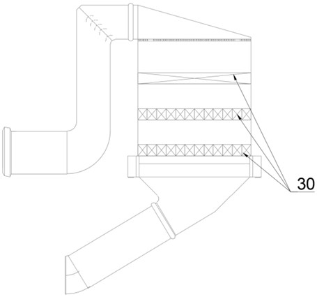
[0052] refer to Figure 1 to Figure 5 , the first embodiment provides a flue flow field measurement device, the flue flow field measurement device includes a streamlined casing 101, the head end of the streamlined casing 101 is connected to a traction rope 103; The sensor 105, the acquisition control circuit 106 and the wireless transmission module 107; the differential pressure sensor 104 is used to acquire the differential pressure signal of the airflow, the differential pressure sensor 104 is electrically connected with the acquisition control circuit 106, and the acquisition control circuit 106 is used to calculate the differential pressure signal Converted into a wind speed signal; the attitude sensor 105 is used to calculate the three-dimensional attitude signal of the flue flow field measurement device in the flue through the three-axis acceleration value and the angular velocity value, the attitude sensor 105 is electrically connected with the acquisition control circuit 106, and the acquisition control circuit 106 passes through The calculation is used to convert the three-dimensional attitude signal into a three-dimensional coordinate signal; the acquisition control circuit 106 is connected to the wireless transmission module 107 to transmit the wind speed signal and the three-dimensional coordinate signal to the analysis system, and display it through images.
[0053] During measurement, the measurement device 10 is hoisted on one of the intersections 201 of the measurement grid 20 by the traction rope 103 . Under the action of the wind force, the traction rope 103 and the measurement device 10 , the measurement device 10 can present an approximate parallel airflow. Attitude; since the interior of the streamlined casing 101 is provided with a differential pressure sensor 104, an attitude sensor 105, a collection control circuit 106 and a wireless transmission module 107, the differential pressure sensor 104 can obtain the differential pressure signal of the airflow, and the differential pressure sensor 104 and the acquisition control circuit 106 Electrically connected, the acquisition control circuit 106 can convert the differential pressure signal into a wind speed signal by calculating; the attitude sensor 105 can calculate the three-dimensional attitude signal of the flue flow field measuring device in the flue through the three-axis acceleration value and angular velocity value. The acquisition control circuit 106 is electrically connected, and the acquisition control circuit 106 can convert the three-dimensional attitude signal into a three-dimensional coordinate signal through calculation; the acquisition control circuit 106 is connected to the wireless transmission module 107, and can transmit the wind speed signal and the three-dimensional coordinate signal to the analysis system, and through the image to show. It can be seen that the flue flow field measurement device and the flue flow field measurement method can not only measure the wind speed of the air flow, but also the flow direction of the air flow, so that the real flow field of the flue can be restored to the maximum extent; The flue flow field measuring device and the flue flow field measuring method are safe and easy to implement.
[0054] It should be noted that the above-mentioned "approximately parallel" means that the posture of the measuring device 10 and the airflow may be parallel in a strict sense, or may be approximately parallel, and there may be a certain deviation in the parallelism between the two.
[0055] Specifically, the acquisition control circuit 106 is connected to the differential pressure sensor 104 and the attitude sensor 105, collects differential pressure information and attitude information, and performs preliminary processing on the data. The acquisition control circuit 106 is connected to the wireless transmission module 107 through a serial port.
[0056] Further, the tail end of the streamlined housing 101 is provided with a tail fin 102, which can enhance the stability of the entire measurement device 10 and avoid large fluctuations in data when collecting data.
[0057] refer to figure 1 , the interior of the streamlined casing 101 is also provided with a power supply battery 108, and the power supply battery 108 is connected to the acquisition control circuit 106 for supplying power to the flue flow field measurement device.
[0058] In this embodiment, the differential pressure sensor 104 includes two ports, one of which is disposed toward the windward side, and the other port is disposed toward the leeward side.
[0059] combine figure 1 and Figure 4 , the differential pressure sensor 104 has two upper and lower ports, the upper port is arranged toward the windward side, and the lower port is arranged toward the leeward side.
[0060] Specifically, the differential pressure sensor 104 is a digital differential pressure sensor. The two pressures of the measured medium of the differential pressure sensor pass into the high and low pressure chambers, and act on the isolation diaphragms on both sides of the delta sensitive element. The filling liquid in the sheet and the element is sent to both sides of the measuring diaphragm, the measuring diaphragm and the electrodes on the insulating sheets on both sides form a capacitor, and the pressure difference between the two air inlets is measured through the change of the capacitance value.
[0061] Please continue to refer to figure 1 , the streamlined shell 101 includes a first section, a middle section and a tail section; the lateral size of the first section is gradually increased from front to back; the lateral size of the middle section remains unchanged from front to back; the lateral size of the tail section is from front to back. Decrease the setting gradually, so that the flue flow field measuring device can maintain a stable attitude under the action of wind.
[0062] The tail fin 102 is connected to the tail section of the streamlined casing 101 .
[0063] refer to figure 2 and image 3 , the flue flow field measurement device also includes a measurement grid 20; the measurement grid 20 includes a plurality of intersections 201; during measurement, the traction rope 103 is connected to one of the intersections 201; , the number of points can be increased or decreased arbitrarily.
[0064] In an embodiment of the present application, the measurement grid 20 is constructed by interweaving a plurality of iron wires in a mesh shape.
[0065] refer to Figure 5 , During the measurement, the measurement grid 20 is arranged between 1 and 2 m above the catalyst 30 of the SCR device. The purpose of this is that after the airflow encounters the catalyst, due to the resistance of the catalyst, an unstable flow field will be generated above the catalyst. Affect the measurement results, so the measurement is arranged at 1~2m above the catalyst.
[0066] Exemplarily, the measurement grid 20 is arranged 1.1 m, 1.2 m, 1.3 m, 1.4 m, 1.5 m, 1.6 m, 1.7 m, 1.8 m, 1.9 m or 2 m above the SCR device catalyst 30 .
[0067] In summary, the measurement process of the flue flow field measurement device is as follows:
[0068] Use the traction rope 103 to hoist the measuring device 10 to the corresponding intersection 201 of the measuring grid 20. After arranging the measuring points, start the fan and wait for the wind speed to stabilize. Under the action of the wind, the measuring device 10 will basically remain in the direction of the airflow. a stable posture;
[0069] The acquisition control circuit 106 is connected to the wireless transmission module 107, and can transmit the wind speed signal and the three-dimensional coordinate signal to the analysis system, and display it through images.

Example Embodiment

[0070] Embodiment 2
[0071] The second embodiment also provides a flue flow field measurement method, comprising the following steps:
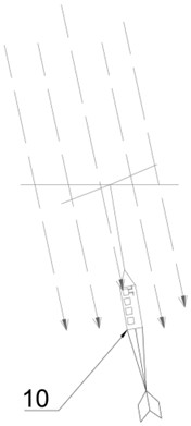
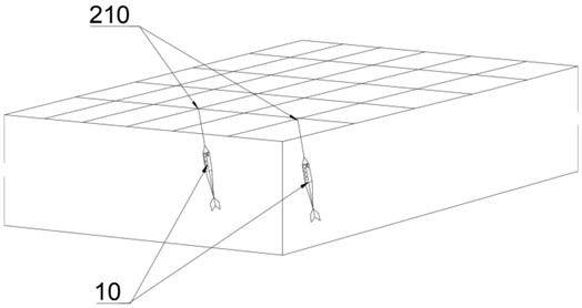
[0072] The measuring device 10 is hoisted in the flue;
[0073] blowing air to the measuring device 10 by means of a fan;
[0074] Under the action of the wind force, the traction rope 103 and the measuring device 10, the measuring device 10 presents an attitude similar to the parallel airflow;
[0075] Obtain differential pressure information through the differential pressure sensor 104 in the measuring device 10, and convert it into a wind speed signal;
[0076] Acquire the three-dimensional attitude signal of the measuring device 10 in the flue by the attitude sensor 105 in the measuring device 10, and convert it into a three-dimensional coordinate signal;
[0077] The wind speed signal and three-dimensional coordinate signal are transmitted to the analysis system and displayed through images.
[0078] In the step of hoisting the measuring device 10 in the flue, a measuring grid 20 including a plurality of intersections 201 needs to be arranged in the flue, and the measuring device 10 is hoisted on one of the intersections 201 by the traction rope 103 .
[0079] The multiple groups of measuring devices 10 are separately hoisted on the corresponding intersections 201 to obtain the average value of the multiple groups of wind speed signals and the average value of the multiple groups of three-dimensional coordinate signals; the average value of the multiple groups of wind speed signals and the multiple groups of three-dimensional coordinate signals The average value of , is transmitted to the analysis system and displayed through images. In this way, arranging multiple groups of measurement devices 10 can improve the accuracy of measurement compared with arranging one group of measurement devices 10 .

PUM

no PUM

Description & Claims & Application Information

We can also present the details of the Description, Claims and Application information to help users get a comprehensive understanding of the technical details of the patent, such as background art, summary of invention, brief description of drawings, description of embodiments, and other original content. On the other hand, users can also determine the specific scope of protection of the technology through the list of claims; as well as understand the changes in the life cycle of the technology with the presentation of the patent timeline. Login to view more.
Why Eureka
Try Eureka