Optical waveguide structure and head-mounted display device

A technology of optical waveguide and film layer structure, applied in optics, optical components, instruments, etc., can solve the problems of difficult to exceed 60°, no fusion of reality, small field of view, etc., to increase the imaging range, increase the field of view, Satisfy the effect of large field of view

Pending Publication Date: 2022-08-02
GOERTEK OPTICAL TECH CO LTD
View PDF7 Cites 0 Cited by
  • Summary
  • Abstract
  • Description
  • Claims
  • Application Information

AI Technical Summary

Problems solved by technology

[0002] At present, VR virtual reality equipment can easily achieve a large field of view above 90°, but VR virtual reality equipment cannot see the outside world through the display screen, that is, it has no ability to integrate reality
Although AR augmented reality devices can penetrate the display screen to see the outside world and can integrate reality, their field of view is generally small and difficult to exceed 60°
It can be seen that the existing VR technology and AR technology have different degrees of deficiencies in terms of user visual experience.

Method used


Image

  • Optical waveguide structure and head-mounted display device
  • Optical waveguide structure and head-mounted display device
  • Optical waveguide structure and head-mounted display device

Examples


Embodiment Construction

[0033] Various exemplary embodiments of the present application will now be described in detail with reference to the accompanying drawings. It should be noted that the relative arrangement of the components and steps, the numerical expressions and numerical values ​​set forth in these embodiments do not limit the scope of the present application unless specifically stated otherwise.

[0034] The following description of at least one exemplary embodiment is merely illustrative in nature and in no way limits the application, its application, or uses in any way.

[0035] Techniques and devices known to those of ordinary skill in the relevant art may not be discussed in detail, but where appropriate, such techniques and devices should be considered part of the specification.

[0036] In all examples shown and discussed herein, any specific values ​​should be construed as illustrative only and not limiting. Accordingly, other instances of the exemplary embodiment may have differe...


PUM


Abstract

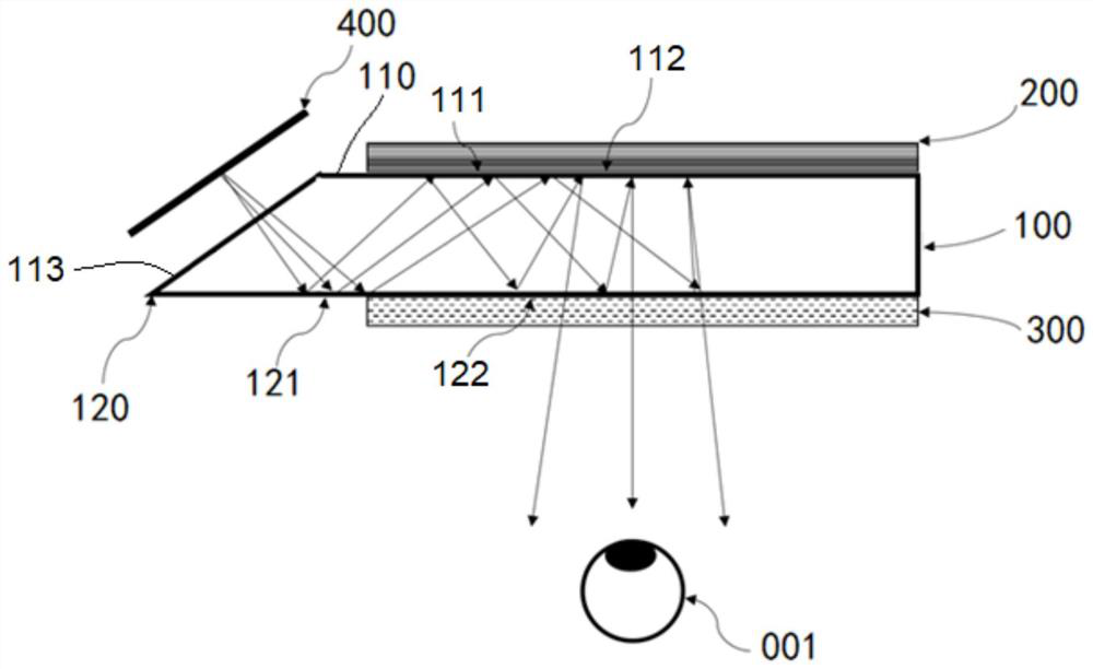
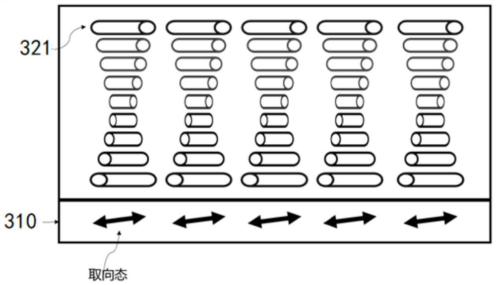
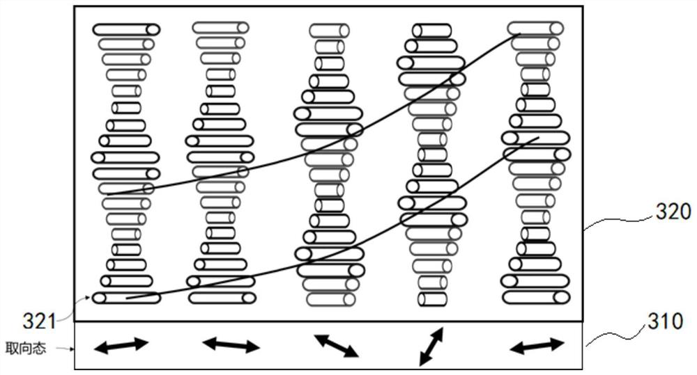
The embodiment of the invention provides an optical waveguide structure and head-mounted display equipment. The optical waveguide structure comprises an optical waveguide body, a volume holographic element and a liquid crystal element, the optical waveguide body comprises a first surface and a second surface which are oppositely arranged, the volume holographic element is arranged on the first surface, and the liquid crystal element is arranged on the second surface; the liquid crystal element is used for selectively diffracting and transmitting light, and first circularly polarized light in a first polarization state in the light is diffracted to the volume holographic element; the volume holographic element is used for enabling the polarization direction of the first circularly polarized light to rotate to form second circularly polarized light in a second polarization state, the second circularly polarized light is diffracted to the liquid crystal element, and the second circularly polarized light is coupled out of the optical waveguide body after being transmitted by the liquid crystal element. The embodiment of the invention provides a large-view-field hybrid virtual reality scheme.

Description

technical field [0001] The embodiments of the present application relate to the technical field of near-eye display imaging, and more particularly, the embodiments of the present application relate to an optical waveguide structure and a head-mounted display device. Background technique [0002] At present, VR virtual reality equipment can easily achieve a large field of view of more than 90°, but VR virtual reality equipment cannot see the outside world through the display screen, that is, it does not have the ability to integrate reality. Although AR augmented reality devices can see the outside world through the display screen and can integrate reality, their field of view is generally small and difficult to exceed 60°. It can be seen that the existing VR technology and AR technology have different degrees of deficiencies in the user's visual experience. SUMMARY OF THE INVENTION [0003] The purpose of this application is to provide an optical waveguide structure and a...

Claims


Application Information

Patent Timeline
IPC IPC(8): G02B27/01
CPCG02B27/0172G02B2027/0174G02B2027/0123G02B2027/0178
Inventor 赵恩饶轶吾晓
Owner GOERTEK OPTICAL TECH CO LTD
Why Eureka
Try Eureka