

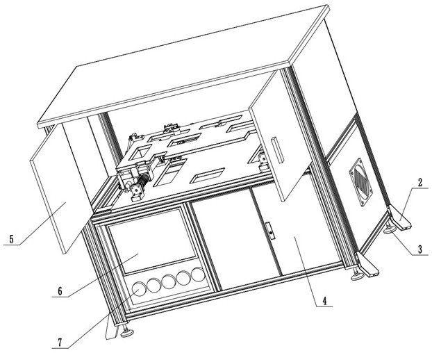
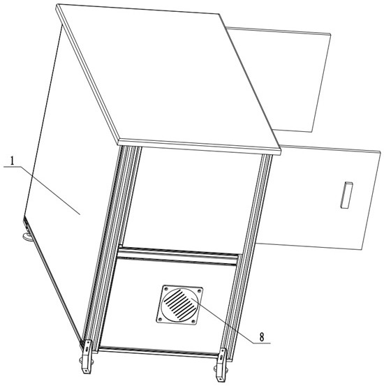
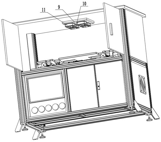
Circulating heat dissipation power distribution cabinet
A technology of circulating heat dissipation and power distribution cabinets, which is applied to the substation/power distribution device shell, electrical components, substation/switch layout details, etc., can solve the problems that the fan is easy to accidentally injure the maintenance personnel, and cannot automatically cut off the power, so as to achieve automatic power off Electricity, convenient maintenance and repair effect
- Summary
- Abstract
- Description
- Claims
- Application Information
AI Technical Summary
Problems solved by technology
Method used
Image

Examples
Embodiment Construction
[0024] The technical solutions of the present invention will be further described in detail below through embodiments and in conjunction with the accompanying drawings. In the following description, numerous specific details are set forth in order to provide a thorough understanding of the present invention. However, the present invention can be implemented in many other ways different from those described herein, and those skilled in the art can make similar improvements without departing from the connotation of the present invention. Therefore, the present invention is not limited by the specific implementation disclosed below.
[0025] In the description of the present invention, it should be noted that the orientations or positional relationships indicated by the terms "upper", "lower", "front", "rear", "left", "right", etc. are based on those shown in the accompanying drawings. The orientation or positional relationship, or the orientation or positional relationship that ...
PUM
 Abstract
Description
Claims
Application Information