Electric motor having a rotor with a block protection sleeve, which

An electric motor and protection sleeve technology, which is applied to synchronous motors with static armatures and rotating magnets, electrical components, electric components, etc., can solve the problems of high manufacturing cost and high reluctance, and achieve easy assembly, The effect of reducing the amount of assembly work

Pending Publication Date: 2022-08-02
SCHAEFFLER TECH AG & CO KG
View PDF1 Cites 0 Cited by
  • Summary
  • Abstract
  • Description
  • Claims
  • Application Information

AI Technical Summary

Problems solved by technology

However, these bonded rotors are relatively expensive to manufacture
Furthermore, the resulting disadvantage of reluctan

Method used


Image

  • Electric motor having a rotor with a block protection sleeve, which
  • Electric motor having a rotor with a block protection sleeve, which
  • Electric motor having a rotor with a block protection sleeve, which

Examples


Example Embodiment

[0033] The drawings are only schematic in nature and are used only for the understanding of the invention. Identical elements are provided with the same reference numerals.

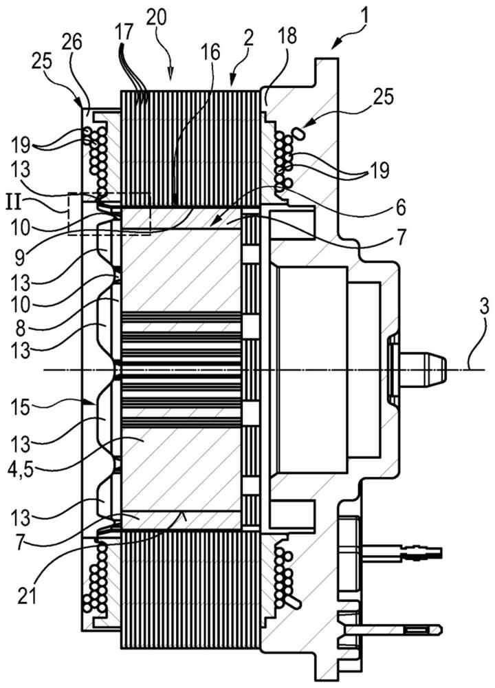
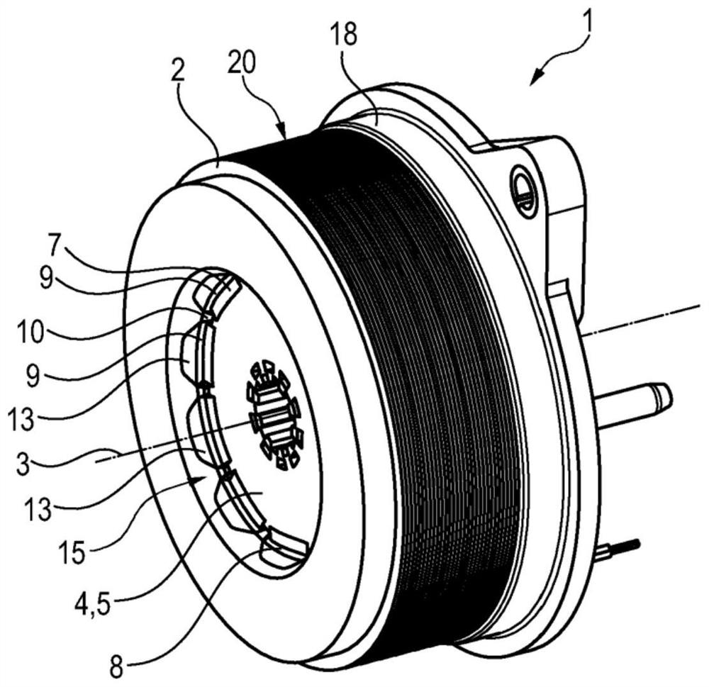
[0034] use figure 1 , image 3 and Figure 12 The basic structure of the electric motor 1 according to the invention can be easily recognized. The electric motor 1 is equipped with a stator 2 of integral annular design. In this embodiment, the stator 2 has a plurality of stator laminations 17 arranged in a stack in the axial direction, ie along the axis of rotation 3 of the rotor 4 of the electric motor 1 . The stator laminations 17 are received on the stator housing / stator carrier 18 . Windings 19 are also provided in a typical manner, which can be figure 1 The sectional view in is seen close to the axial end face of the stack 20 on the stator laminations 17 .

[0035] Furthermore, a rotatably mounted rotor 4 is arranged radially inside the stator 2 (relative to the axis of rotation 3). In this e...


PUM


Abstract

The invention relates to an electric motor (1) comprising a stator (2) and a rotor (4) mounted in a rotatable manner relative to the stator (2) about an axis of rotation (3). The rotor (4) also has: a main part (5); a plurality of magnet elements (7) distributed in the circumferential direction and received on the radial face (6) of the main part (5) in a mutually spaced manner; and a burst protection sleeve (8) covering the main part (5) and the magnet element (7). The burst protection sleeve (8) has: a plurality of cover sections (9), each of which directly contacts the magnet element (7); and a plurality of bridging regions (10) which connect two adjacent cover sections (9) together, the burst protection sleeve (8) being used to support the magnet element (7) directly relative to the main part (5), and the bending strength of the bridging regions (10) in the circumferential direction being lower than that of the cover sections (9).

Description

technical field [0001] The invention relates to an electric motor, preferably used in an actuator of an actuating device of a motor vehicle, the electric motor having a stator and a rotor rotatably mounted about an axis of rotation with respect to the stator, wherein the rotor also having: a main part; a plurality of magnet elements distributed in a circumferential direction and received on a radial face of the main part in a spaced manner from each other; and a burst protection sleeve, the burst protection sleeve The main portion and the magnet element are covered, and wherein the burst protection sleeve has: a plurality of cover segments, each of the plurality of cover segments directly contacting the magnet element; and a plurality of bridging regions, the plurality of A bridging area connects two adjacent coverage segments together. Background technique [0002] Universal electric motors are well known in the prior art. Thus, for example, DE 10 2018 108 595 A1 disclose...

Claims


Application Information

Patent Timeline
IPC IPC(8): H02K1/278
CPCH02K1/2781H02K1/28H02K21/14H02K2213/03
Inventor 朱利安·博蒂奥夫马库斯·迪特里希克里斯蒂安·布鲁纳
Owner SCHAEFFLER TECH AG & CO KG
Why Eureka
Try Eureka