Hydraulic machine for machining shaft sleeve parts and machining process

A technology of parts processing and hydraulic press, which is applied in the field of hydraulic press and processing technology for the processing of shaft sleeve parts, can solve the problem that the specific position of the bulging cavity on the metal cylinder cannot be changed, and achieve the effect of easy cleaning

Active Publication Date: 2022-08-05
嘉兴巨盈金属制品有限公司
View PDF10 Cites 1 Cited by
  • Summary
  • Abstract
  • Description
  • Claims
  • Application Information

AI Technical Summary

Problems solved by technology

[0004] In the process of implementing the present application, the inventors found that there are at least the following problems in this technology. Due to the fixed depth of the positioning groove, the outwardly bulged position on the metal cylinder is always located at the designated position of the metal cylinder, which cannot be changed according to the actual situation. The specific location of the bulging cavity on the metal cylinder

Method used


Image

  • Hydraulic machine for machining shaft sleeve parts and machining process
  • Hydraulic machine for machining shaft sleeve parts and machining process
  • Hydraulic machine for machining shaft sleeve parts and machining process

Examples


Embodiment Construction

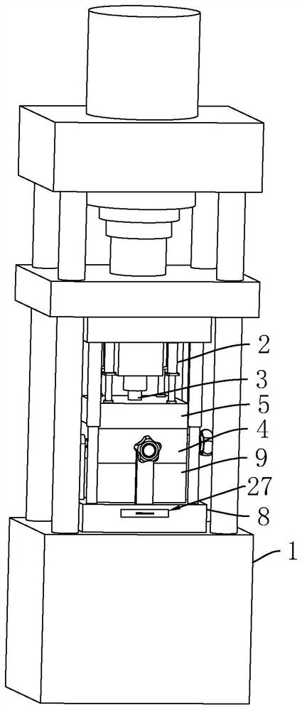
[0045] Attached to the following Figure 3-8 This application will be described in further detail.

[0046] The embodiment of the present application discloses a hydraulic press for processing a shaft sleeve type part. refer to image 3 and Figure 4 , including a hydraulic press body 1 fixed on the ground, a lower die 4 arranged on the workbench of the hydraulic press body 1, a number of oil cylinders 2 fixed on the hydraulic press body 1, an upper die 5 connected to the oil cylinder 2 and facing the lower die 4 and The extrusion cylinder 3 fixed on the punch of the main body 1 of the hydraulic press. The oil cylinder 2 is arranged vertically and the cylinder body is fixed on the hydraulic machine body 1 by bolts. The upper die 5 is fixed on the output end of the oil cylinder 2 and drives the upper die 5 to move in the vertical direction under the action of the oil cylinder 2 .

[0047] refer to Figure 4 and Figure 5 , the upper end face of the lower mold 4 and the lo...


PUM


Abstract

The hydraulic machine comprises a hydraulic machine body, a lower die arranged on a workbench, an oil cylinder arranged on the hydraulic machine body, an upper die connected to the oil cylinder and an extrusion cylinder connected to a punch and used for extruding a metal cylinder. The lower die and the upper die are internally provided with positioning grooves used for limiting the metal cylinders and containing grooves enabling the metal cylinders to form outward bulging, an adjusting base is connected to the workbench, the lower die is fixed to the adjusting base, the positioning grooves vertically penetrate through the lower die and the upper die, the extrusion cylinders are arranged in the corresponding positioning grooves in a penetrating mode, and an installation groove is formed in the upper end face of the adjusting base. An adjusting block is arranged in the mounting groove in a sliding mode, an adjusting rod which is vertically arranged and penetrates through the positioning groove is fixed to the adjusting block, a positioning rod which penetrates through the metal cylinder is coaxially arranged at the upper end of the adjusting rod, and an adjusting mechanism which drives the adjusting block to move in the vertical direction is arranged in the mounting groove. The device has the effect of conveniently forming outward bulges at different positions of the metal cylinder.

Description

technical field [0001] The present application relates to the field of hydraulic presses, and in particular, to a hydraulic press and a processing technology for processing shaft sleeve parts. Background technique [0002] Hydraulic press is a kind of working medium that uses liquid as the working medium, and is used to transmit energy to realize various processes. [0003] figure 1 for the metal cylinder to be processed, figure 2 It is a processed metal cylinder. Before processing, the staff will install the lower die on the working table of the hydraulic press. The lower die is provided with a positioning that penetrates the metal cylinder and prevents the metal cylinder from being deformed inward during the processing. Rod, the staff will also install an oil cylinder on the hydraulic press, an upper die is installed on the oil cylinder, a coaxial positioning groove is formed in the upper and lower molds and is fitted with the outer wall of the metal cylinder, and the p...

Claims


Application Information

Patent Timeline
Patent Type & Authority Applications(China)
IPC IPC(8): B21D22/26B21D37/04B21D45/02B21D53/10
CPCB21D22/26B21D37/04B21D45/02B21D53/10
Inventor 彭磊吕秋建陈新平
Owner 嘉兴巨盈金属制品有限公司
Why Eureka
Try Eureka