Air floatation supporting mechanism

A support mechanism and air flotation technology, which is applied in the direction of mechanical equipment, bearings, shafts and bearings, etc., can solve the problems that the cylinder occupies a large space, cannot meet the support requirements of the workpiece table, and the vertical bearing capacity of the cylinder rod of the cylinder is limited.

Pending Publication Date: 2022-08-05
BEIJING SEMICON EQUIP INST THE 45TH RES INST OF CETC
0 Cites 0 Cited by

AI-Extracted Technical Summary

Problems solved by technology

However, the cylinder occupies a large space, and the vertical bearing capacity of the cylinder rod of the c...

Method used

Preferably, the aperture of a plurality of air flotation holes 26 is 0.12mm-0.18mm, so that gas can be stably blown to the support surface by a plurality of air flotation holes 26, ensuring that the thickness of the support gas film formed is even, and the floating process Stable and reliable, without skewing.
[0047] Preferably, as shown in FIG. 3, while the abutting portion seals against the inner sidewall of the cylinder body 1 through the first seal 12, there is a ga...

Abstract

The invention relates to the technical field of precision equipment, in particular to an air floatation supporting mechanism. The air floatation supporting mechanism comprises a cylinder body, an air floatation assembly and a driving piece, the cylinder body is connected below the workpiece table, the upper end of the air floatation assembly is slidably connected into the cylinder body, and the lower end face of the air floatation assembly faces the supporting face. The cylinder body can be communicated with an external cylinder body air source so as to convey air into the cylinder body and downwards push the air floatation assembly to be close to the supporting surface; the driving piece can drive the air floating assembly to move upwards to be away from the supporting face. In the using process, when the workpiece table needs to suspend, firstly, air is introduced into the air cylinder to push the air floating assembly to move downwards to make contact with the supporting face, then the temporary supporting structure is removed, the air floating assembly is started, and the air floating assembly blows air towards the supporting face to form a supporting air film; therefore, the air floatation supporting mechanism and the workpiece table float upwards and suspend above the supporting face, and in the suspension state, the cylinder body and the air floatation assembly can provide enough supporting force for the workpiece table.

Application Domain

Gas cushion bearingsBearing components

Technology Topic

EngineeringCylinder block +1

Image

  • Air floatation supporting mechanism
  • Air floatation supporting mechanism
  • Air floatation supporting mechanism

Examples

  • Experimental program(1)

Example Embodiment

[0028] The technical solutions of the present invention will be clearly and completely described below with reference to the accompanying drawings. Obviously, the described embodiments are a part of the embodiments of the present invention, but not all of the embodiments.
[0029] The components of the embodiments of the invention generally described and shown in the drawings herein may be arranged and designed in a variety of different configurations. Thus, the following detailed description of the embodiments of the invention provided in the accompanying drawings is not intended to limit the scope of the invention as claimed, but is merely representative of selected embodiments of the invention.
[0030] Based on the embodiments of the present invention, all other embodiments obtained by those of ordinary skill in the art without creative efforts shall fall within the protection scope of the present invention.
[0031] In the description of the present invention, it should be noted that the terms "center", "upper", "lower", "left", "right", "vertical", "horizontal", "inner", "outer", etc. The indicated orientation or positional relationship is based on the orientation or positional relationship shown in the accompanying drawings, which is only for the convenience of describing the present invention and simplifying the description, rather than indicating or implying that the indicated device or element must have a specific orientation or a specific orientation. construction and operation, and therefore should not be construed as limiting the invention. Furthermore, the terms "first", "second", and "third" are used for descriptive purposes only and should not be construed to indicate or imply relative importance.
[0032] In the description of the present invention, it should be noted that the terms "installed", "connected" and "connected" should be understood in a broad sense, unless otherwise expressly specified and limited, for example, it may be a fixed connection or a detachable connection Connection, or integral connection; can be mechanical connection, can also be electrical connection; can be directly connected, can also be indirectly connected through an intermediate medium, can be internal communication between two elements. For those of ordinary skill in the art, the specific meanings of the above terms in the present invention can be understood in specific situations.
[0033] Refer below Figure 1 to Figure 6 Air flotation support mechanisms according to some embodiments of the present application are described.
[0034] The present application provides an air-floating support mechanism, which is arranged between a workpiece table and a support surface, so that the workpiece table can be suspended relative to the support surface.
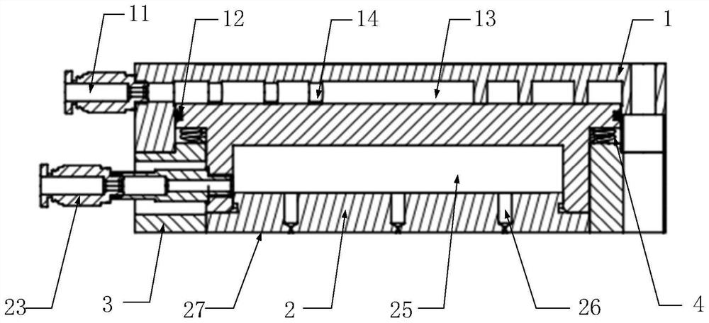
[0035] like figure 1 and figure 2 As shown, the air-floating support mechanism includes a cylinder block 1, an air-float assembly 2 and a driving member. For a horizontally arranged workpiece table and a horizontal support surface located below the workpiece table, the cylinder block 1 is arranged in a vertical direction, and the cylinder block 1 is used to be arranged below the workpiece table and connected to the workpiece table, so that the workpiece table is mounted on the end cover of the upper end of the cylinder block 1 to support the workpiece table through the cylinder block 1 . The lower end surface of the air flotation assembly 2 faces the supporting surface, and the upper end of the air flotation assembly 2 is slidably connected to the cylinder body 1, so that the air flotation assembly 2 can reciprocate in the vertical direction relative to the cylinder A supporting surface, and the outer side wall of the upper end of the air flotation component 2 located in the cylinder body 1 is in sealing abutment with the inner side wall of the cylinder body 1 .
[0036]A first joint 11 is provided on the side wall of the cylinder block 1. The chamber in the cylinder block 1 above the air flotation assembly 2 is a driving chamber 13. The driving chamber 13 communicates with the first joint 11, and the driving chamber 13 It can communicate with the external cylinder block 1 gas source through the first joint 11, so that gas can be delivered to the driving chamber 13 through the external cylinder block 1 gas source, so that the driving chamber 13 has a predetermined pressure and pushes The air flotation assembly 2 moves downward to approach the supporting surface below.
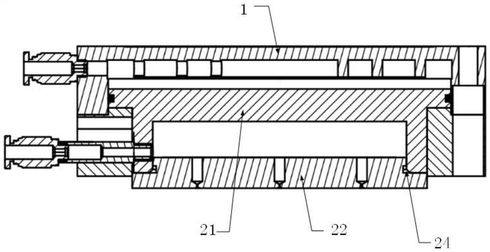
[0037] It should be noted that when the first joint 11 is not in communication with the air source of the cylinder 1, the driving chamber 13 can communicate with the external environment through the first joint 11, so that when the air flotation assembly 2 moves upward, the driving chamber 13 The gas inside can be discharged through the first joint 11, so that the air flotation assembly 2 can move upward smoothly.
[0038] The driving member is arranged in the cylinder block 1 and is located between the cylinder block 1 and the air-floating assembly 2, and the driving member can drive the air-floating assembly 2 to move upwards so as to be away from the supporting surface below. For example, the driving member is an elastic member 4, two ends of the elastic member 4 are respectively abutted against the cylinder 1 and the air flotation assembly 2, and the elastic force of the elastic member 4 makes the air flotation assembly 2 have an upward movement trend. When the driving chamber 13 is filled with gas and has a predetermined pressure, the air flotation assembly 2 can overcome the elastic force of the elastic member 4 to move downward to approach the supporting surface; when the driving chamber 13 is communicated with the external environment, the air flotation assembly 2 Driven by the elastic member 4, it can move upward to be away from the support surface.
[0039] The lower end surface of the air flotation assembly 2 is an air flotation surface 27, and the air flotation surface 27 faces the supporting surface. When the air flotation assembly 2 is working, the air flotation assembly 2 can blow air toward the supporting surface below, so as to connect the supporting surface and the air flotation assembly with air. A supporting air film is formed between the air-floating surfaces 27 of 2 , so that the air-floating component 2 is floated upwards to be suspended above the supporting surface.
[0040] For example, combining figure 1 and Figure 4 As shown in the figure, an air flotation chamber 25 is formed inside the air flotation component 2, and a plurality of air flotation holes 26 are opened on the air flotation surface 27 of the air flotation component 2, and the plurality of air flotation holes 26 are distributed on the air flotation surface 27 in concentric circles. , and the plurality of air flotation holes 26 are all communicated with the air flotation chamber 25 . The air flotation chamber 25 can be communicated with an external air flotation air source, so that the air can be transported into the air flotation chamber 25 through the air flotation air source, and the air in the air flotation chamber 25 can be blown to the support surface through the air flotation hole 26 , so as to form a supporting air film between the supporting surface and the air bearing surface 27 .
[0041] Preferably, the apertures of the plurality of air flotation holes 26 are all 0.12mm-0.18mm, so that the gas can be stably blown to the supporting surface through the plurality of air flotation holes 26, so as to ensure that the thickness of the formed supporting gas film is uniform, and the floating process is stable and reliable. Skew does not occur.
[0042] In the actual use process, when the workpiece table does not need to be suspended, other temporary support structures can be set between the workpiece table and the support surface to support the workpiece table on the support surface; at this time, such as figure 1 As shown, the air flotation assembly 2 does not work, and the driving chamber 13 in the cylinder block 1 is communicated with the external environment. When not in operation, the air-floating surface 27 of the air-floating assembly 2 can be prevented from being damaged by pressure caused by the air-floating surface 27 of the air-floating assembly 2 being pressed on the supporting surface for a long time.
[0043] like figure 2 As shown in the figure, when it is necessary to activate the air flotation assembly 2 to suspend the workpiece table, gas is first introduced into the cylinder to push the air flotation assembly 2 downward to contact with the support surface, and then the temporary support structure is removed and the air flotation assembly 2 is activated , so that the air flotation assembly 2 is blown toward the support surface to form a supporting air film, so that the air flotation support mechanism and the workpiece table are floated upward and suspended above the support surface, and in the suspended state, the cylinder block 1 and the air flotation assembly 2 can be Provide sufficient support for the workpiece table.
[0044] In an embodiment of the present application, preferably, as figure 1 and figure 2 As shown, the air float assembly 2 includes a piston member 21 and an air float member 22. The upper end of the piston member 21 is slidably connected to the cylinder 1, and the lower end of the piston member 21 is connected to the air float member 22, so that the air float member 22 is in contact with the supporting surface. face, and the lower end surface of the piston member 21 is formed with a concave portion, so as to form the above-mentioned air-floating chamber 25 between the piston member 21 and the air-floating member 22, combined with Figure 4 and Figure 5 As shown, the air flotation holes 26 are opened on the air flotation member 22 , so that the gas in the air flotation chamber 25 is blown to the lower supporting surface through the air flotation holes 26 on the air flotation member 22 .
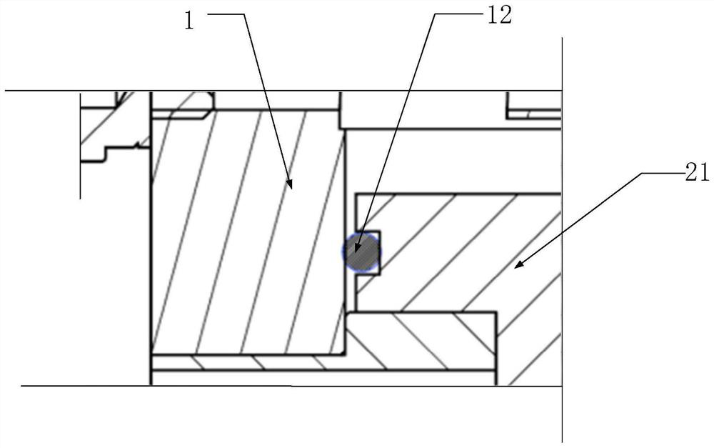
[0045] Preferably, as figure 1 and image 3 As shown, the outer side wall of the upper end of the piston member 21 located in the cylinder body 1 is provided with an abutting portion along the circumferential direction of the piston member 21, and the outer side wall of the abutting portion faces the inner side wall of the cylinder body 1, and the abutting portion is The outer side wall is provided with a first sealing groove along its circumferential direction, and a first sealing member 12 is installed in the first sealing groove. The part is in sliding fit with the cylinder block 1 .
[0046] Preferably, the first sealing member 12 may be a star-shaped sealing ring or a Y-shaped sealing ring.
[0047] Preferably, as image 3 As shown, while the abutting portion is sealed against the inner side wall of the cylinder 1 through the first sealing member 12, there is a predetermined gap between the outer side wall of the abutting portion and the inner side wall of the cylinder 1, so that the piston member 21 During the descending process, air tightness can be ensured, and parallelism decoupling can be realized at the same time, so as to prevent the air flotation component 2 from colliding with the cylinder block 1 during the ascending and descending process, and prevent the inner wall of the cylinder block 1 from being damaged and affecting the air tightness.
[0048] Preferably, the gap between the outer side wall of the abutting portion and the inner side wall of the cylinder block 1 is 0.15mm-0.25mm.
[0049] Preferably, the material of the piston member 21 is a tin bronze material with good wear resistance.
[0050] In one embodiment of the present application, as figure 1 As shown, preferably, the lower end of the cylinder block 1 is provided with a support member 3 , and the support member 3 is arranged around the air flotation assembly 2 and is slidably matched with the air flotation assembly 2 . The driving member is an elastic member 4, and the elastic member 4 is arranged between the supporting member 3 and the abutting portion. The floating assembly 2 abuts against, so that the air floating assembly 2 can move upward under the driving of the elastic member 4 .
[0051] Preferably, the number of elastic members 4 is multiple, and the multiple elastic members 4 are distributed at intervals around the circumference of the air flotation assembly 2, so as to provide a balanced elastic driving force to the air flotation assembly 2 through the plurality of elastic members 4, so that the air flotation assembly 2 is provided with a balanced elastic driving force. The assembly 2 is able to maintain vertical upward movement.
[0052] In this embodiment, preferably, as figure 1 As shown, the air-floating member 22 and the piston member 21 are connected by fasteners such as fastening bolts. The upper surface of the air-floating member 22 is formed with a raised portion, and the raised portion can be inserted into the recessed portion of the piston member 21. And the outer side wall of the convex part faces the inner side wall of the concave part; the outer side wall of the convex part is provided with a second sealing groove around the circumference of the convex part, and a second sealing member 24 is installed in the second sealing groove , the protruding portion can seal against the second sealing member 24 and the inner side wall of the concave portion, so that the connection between the air flotation member 22 and the piston member 21 is kept sealed, and the gas entering the air flotation chamber 25 is guaranteed to pass through the air flotation hole. 26 blows down to the support surface, thereby forming a stable support air film between the air bearing surface 27 and the support surface.
[0053] Preferably, as figure 1 As shown, the side wall of the piston member 21 is provided with a second joint 23, the second joint 23 communicates with the air flotation chamber 25, and the air flotation chamber 25 communicates with the external air flotation air source through the second joint 23 .
[0054] Preferably, as figure 1 and figure 2 As shown, an elongated hole is opened at the position opposite to the second joint 23 of the support member 3, and the second joint 23 can be protruded through the elongated hole to communicate with an external air flotation air source.
[0055] The length direction of the elongated hole is along the vertical direction. When the air flotation assembly 2 moves up and down, the second joint 23 can move up and down in the elongated hole.
[0056] In an embodiment of the present application, preferably, as figure 1 and Image 6 As shown, an end cover is formed on the top of the cylinder block 1, and an annular protrusion 14 is formed on the side of the end cover facing the inside of the cylinder block 1. When the air flotation assembly 2 is driven upward by the elastic member 4, the piston member 21 can move to abut against the annular protrusion 14, so as to ensure the drive chamber 13 with a predetermined space above the air flotation assembly 2 at this time, and to enable the upper end of the piston member 21 to stably abut on the protrusion without skewing .
[0057] Preferably, as figure 1 and Image 6 As shown, the number of annular protrusions 14 is multiple, and the plurality of annular protrusions 14 are distributed in concentric circles. At the same time, the interior of the driving chamber 13 can be divided into a plurality of annular grooves by a plurality of concentric annular protrusions 14. When the cylinder body 1 is inflated and deflated, the air pressure in the cylinder body 1 can be uniformly loaded according to the annular groove or Release to avoid the air flotation assembly 2 being tilted due to high air pressure on one side.
[0058] It should be noted that, in order to provide stable support for the workpiece table, usually at least three of the air-bearing support mechanisms are arranged between the workpiece table and the support surface, that is, the workpiece table is mounted on the cylinders of the at least three air-bearing support mechanisms. 1 on.
[0059] Finally, it should be noted that the above embodiments are only used to illustrate the technical solutions of the present invention, but not to limit them; although the present invention has been described in detail with reference to the foregoing embodiments, those of ordinary skill in the art should understand that: The technical solutions described in the foregoing embodiments can still be modified, or some or all of the technical features thereof can be equivalently replaced; and these modifications or replacements do not make the essence of the corresponding technical solutions deviate from the technical solutions of the embodiments of the present invention. scope.

PUM

PropertyMeasurementUnit
Aperture0.12 ~ 0.18mm

Description & Claims & Application Information

We can also present the details of the Description, Claims and Application information to help users get a comprehensive understanding of the technical details of the patent, such as background art, summary of invention, brief description of drawings, description of embodiments, and other original content. On the other hand, users can also determine the specific scope of protection of the technology through the list of claims; as well as understand the changes in the life cycle of the technology with the presentation of the patent timeline. Login to view more.
Why Eureka
Try Eureka