Aircraft undercarriage driving device, aircraft undercarriage and aircraft

A driving device and a technology for an aircraft, applied in the field of aircraft, can solve the problems of unmanned aerial vehicle being unable to land normally and safely, poor positioning of the tripod, affecting the shooting quality, etc., so as to avoid damage accidents, ensure normal and safe landing, and ensure the effect of aerial photography.

Active Publication Date: 2015-07-22
ZEROTECH (BEIJING) INTELLIGENCE TECH CO LTD
View PDF5 Cites 7 Cited by
  • Summary
  • Abstract
  • Description
  • Claims
  • Application Information

AI Technical Summary

Problems solved by technology

[0004] It can be seen from the above that stability is the key factor for the quality of aerial photography of UAVs. The tiny vibrations generated during the flight will have a great impact on the quality of aerial photography, and the tripod itself of the aircraft has a certain weight. , especially when the tripod is retracted to a horizontal position, if the tripod is not positioned stably, the whole body will vibrate, which will affect the shooting quality. Further, for the movable mechanism of the UAV tripod In general, it is a technical difficulty to achieve its stable and precise positioning and maintain good stability during flight. Technicians in the industry have made research and development improvements to this problem, but the results are not satisfactory.
[0005] On the other hand, when the unmanned aerial vehicle lands, it needs to provide enough support to support the body when the tripod is lowered. If the tripod is not properly positioned at this time, the UAV will not be able to land normally and safely, and in severe cases, the body will be damaged.

Method used


Image

  • Aircraft undercarriage driving device, aircraft undercarriage and aircraft
  • Aircraft undercarriage driving device, aircraft undercarriage and aircraft
  • Aircraft undercarriage driving device, aircraft undercarriage and aircraft

Examples


Embodiment Construction

[0056] In order to make the purpose, technical solutions and advantages of the embodiments of the present invention more clear, specific embodiments will be described in detail below with reference to the accompanying drawings.

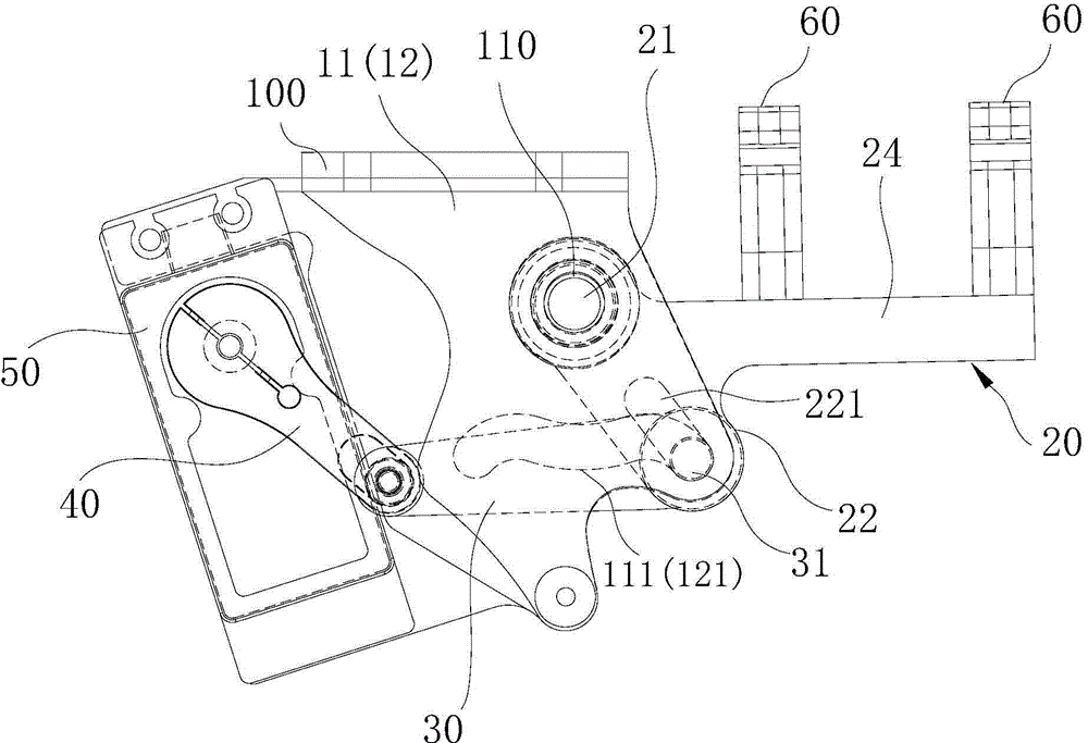
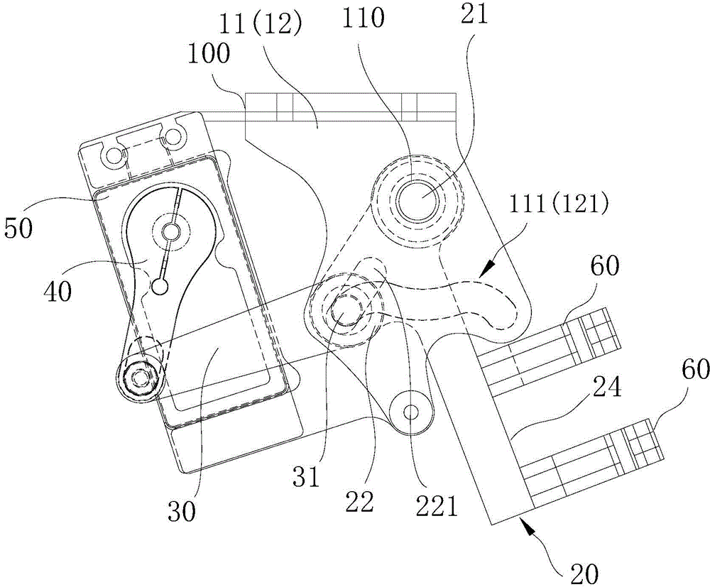
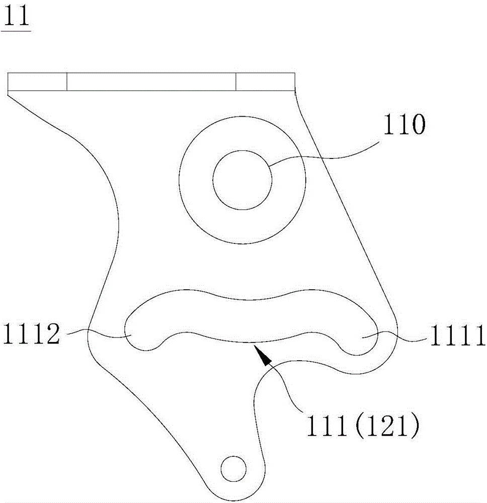
[0057] Please refer to figure 1 , figure 2 , Figure 6 , Figure 7 and Figure 8 ,in figure 1 It is a schematic perspective view of the structure when the tripod of the aircraft tripod driving device of the present invention is retracted, figure 2 It is a schematic perspective view of the structure when the tripod of the aircraft tripod driving device of the present invention is put down, Figure 6 , Figure 7 and Figure 8They are three-dimensional schematic diagrams of the three-dimensional structure of the aircraft stand drive device at different angles. As shown in the figure, the aircraft stand drive device of the present invention mainly includes: a first arm plate 11 and a second arm plate 12, which are fixed to the aircraft Below the...


PUM


Abstract

The invention discloses an aircraft undercarriage driving device, an aircraft undercarriage and an aircraft. The aircraft undercarriage driving device comprises a first support arm plate, a second support arm plate, an undercarriage seat, a driven arm and an actuating arm, wherein the first support arm plate and the second support arm plate are fixedly connected below a rack, a first chute is formed in the first support arm plate, and a second chute is formed in the second support arm plate; the undercarriage seat can be rotationally arranged between the first support arm plate and the second support arm plate through a rotating shaft, and a hinged part is bulged on the undercarriage seat; one end of the driven arm is hinged to the hinged part through a hinged shaft, and two ends of the hinged shaft are glidingly clamped to the first chute and the second chute respectively; one end of the actuating arm is hinged to the other end of the driven arm, and the other end of the actuating arm is connected with an actuator. The aircraft undercarriage can be stably and accurately positioned in retracting and deploying positions.

Description

technical field [0001] The invention relates to the technical field of aircraft, in particular to an aircraft stand driving device, an aircraft landing gear and an aircraft. Background technique [0002] In recent years, with the rapid development of unmanned aerial vehicle technology, the application range of multi-axis unmanned aerial vehicles has become wider and wider. For example, it has a wide range of applications in professional fields such as aerial photography, measurement, disaster control, and real-time monitoring. At the same time, The requirements for the shooting quality of drones are getting higher and higher, and the key factor affecting the quality of drone aerial photography is stability, including the stability of drone flight and the stability of gimbal rotation. [0003] The existing drone shooting is to install a camera device on the unmanned aerial vehicle, and the camera device is driven by the multi-directional rotation of the pan / tilt, thereby real...

Claims


Application Information

Patent Timeline
Patent Type & Authority Applications(China)
IPC IPC(8): B64C25/10B64C25/20
CPCY02T50/40
Inventor 唐杰杨建军
Owner ZEROTECH (BEIJING) INTELLIGENCE TECH CO LTD
Why Eureka
Try Eureka