
Rotating shaft locking mechanism for mechanical design

A locking mechanism and mechanical design technology, which is applied to mechanical equipment, gear transmission mechanisms, brake actuators, etc., can solve the problems of locking mechanism wear and shaft locking, so as to achieve firm locking, improve locking effect, and improve locking efficiency. effective effect

Pending Publication Date: 2022-08-05
BAYIN GUOLENG TECH COLLEGE
View PDF0 Cites 0 Cited by
  • Summary
  • Abstract
  • Description
  • Claims
  • Application Information

AI Technical Summary

Problems solved by technology

[0003] The existing rotating shaft usually works in a vibrating environment for a long time, but the existing mechanical design uses a rotating shaft locking mechanism, which often uses friction to lock the rotating shaft. Insecure locking, wear and tear on the locking mechanism

Method used


Image

  • Rotating shaft locking mechanism for mechanical design
  • Rotating shaft locking mechanism for mechanical design
  • Rotating shaft locking mechanism for mechanical design

Examples


Embodiment Construction

[0027] The technical solutions in the embodiments of the present invention will be clearly and completely described below with reference to the accompanying drawings in the embodiments of the present invention. Obviously, the described embodiments are only a part of the embodiments of the present invention, but not all of the embodiments.

[0028] In the description of the present invention, it should be understood that the terms "upper", "lower", "front", "rear", "left", "right", "top", "bottom", "inside", " The orientation or positional relationship indicated by "outside" is based on the orientation or positional relationship shown in the accompanying drawings, and is only for the convenience of describing the present invention and simplifying the description, rather than indicating or implying that the indicated device or element must have a specific orientation, so as to The specific orientation configuration and operation are therefore not to be construed as limitations of...


PUM


Abstract

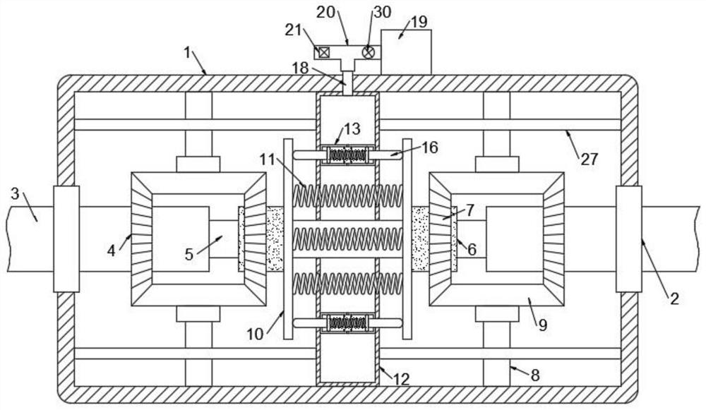
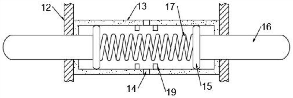
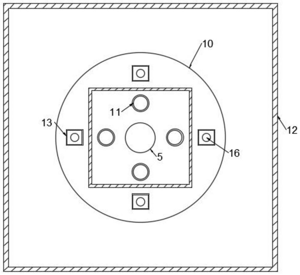
The invention discloses a rotating shaft locking mechanism for mechanical design, which comprises a locking box, fixing rings are fixedly inserted in the two side walls of the locking box, rotating shafts are inserted in the two fixing rings, one ends, located in the locking box, of the two rotating shafts are communicated and fixedly connected with a connecting shaft, and the other ends of the two rotating shafts are communicated and fixedly connected with the connecting shaft. The outer wall of the connecting shaft is sleeved with two movable rings in a sliding mode, a limiting mechanism is arranged between each movable ring and the connecting shaft, and each limiting mechanism comprises a sliding block which is fixedly connected to the outer wall of the connecting shaft and arranged on the inner wall of the corresponding movable ring in a sliding mode. According to the locking mechanism, locking of the rotating shaft is completed through locking caused by meshing of the third bevel gear, the first bevel gear and the second bevel gear on the same side, firm locking of the rotating shaft is achieved, the problem that locking of the rotating shaft is not firm through friction force traditionally is solved, and the locking effect of the locking mechanism is improved.

Description

technical field [0001] The invention relates to the technical field of mechanical equipment, in particular to a shaft locking mechanism for mechanical design. Background technique [0002] The machinery industry is the most basic industrial industry. In mechanical design, the rotating shaft is often used to transmit power. The rotating shaft has the advantages of accurate transmission and high transmission efficiency. When using a rotating shaft drive, a braking and locking mechanism needs to be designed to prevent the rotating shaft from rotating when it needs to stop. [0003] The existing rotating shaft usually works in a vibration environment for a long time, but the existing mechanical design uses a rotating shaft locking mechanism, which often uses friction to lock the rotating shaft, so that in a long-term vibration environment, it is easy to cause the locking mechanism to rotate. Insufficient locking and wear of the locking mechanism. SUMMARY OF THE INVENTION [...

Claims


Application Information

Patent Timeline
IPC IPC(8): F16D63/00F16D65/18F16F15/067F16D121/04
CPCF16D63/006F16D65/183F16F15/067F16D2121/04
Inventor 张茫茫柴春花
Owner BAYIN GUOLENG TECH COLLEGE
Learn More