Battery-replaceable three-phase charge-control intelligent electric energy meter

A smart electric energy meter, replaceable technology, applied in the direction of measuring electric variables, instruments, measuring devices, etc., can solve the problems of long time-consuming installation and disassembly, difficulty in realization, etc., to save operation steps, ensure detection accuracy, and quickly The effect of installation and removal

Pending Publication Date: 2022-08-05
江苏苏源杰瑞科技有限公司
View PDF0 Cites 0 Cited by
  • Summary
  • Abstract
  • Description
  • Claims
  • Application Information

AI Technical Summary

Problems solved by technology

[0004] In order to overcome the above-mentioned defects of the prior art, the present invention provides a battery-replaceable three-phase cost-controlled smart energy meter. The technical problem to be solved by the present invention is: the three-phase cost-controlled smart energy meter in the prior art Generally, it is fixed on the wall through several installation holes and several expansion screws opened on the surface. Not only will the installation and disassembly process take a long time, it is difficult to achieve rapid installation and disassembly, but also the wall needs to be repaired beforehand. Positioning and drilling, when the drilling position is skewed, it will cause the installation of the electric energy meter to be skewed, which will affect the detection accuracy of the electric energy meter, and the screws fixing the electric energy meter are easily loosened by external force, making the electric energy meter not fixed enough Strong, prone to drop damage phenomenon

Method used


Image

  • Battery-replaceable three-phase charge-control intelligent electric energy meter
  • Battery-replaceable three-phase charge-control intelligent electric energy meter
  • Battery-replaceable three-phase charge-control intelligent electric energy meter

Examples


Embodiment Construction

[0032] The technical solutions in the embodiments of the present invention will be clearly and completely described below with reference to the accompanying drawings in the embodiments of the present invention. Obviously, the described embodiments are only a part of the embodiments of the present invention, but not all of the embodiments. Based on the embodiments of the present invention, all other embodiments obtained by those of ordinary skill in the art without creative efforts shall fall within the protection scope of the present invention.

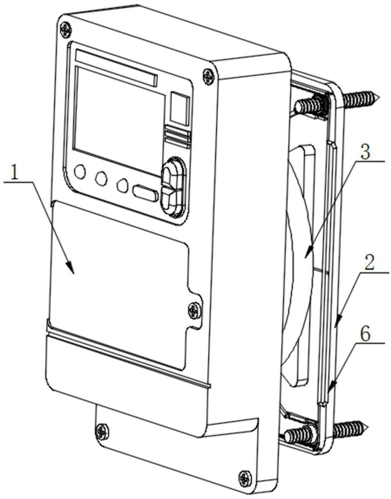
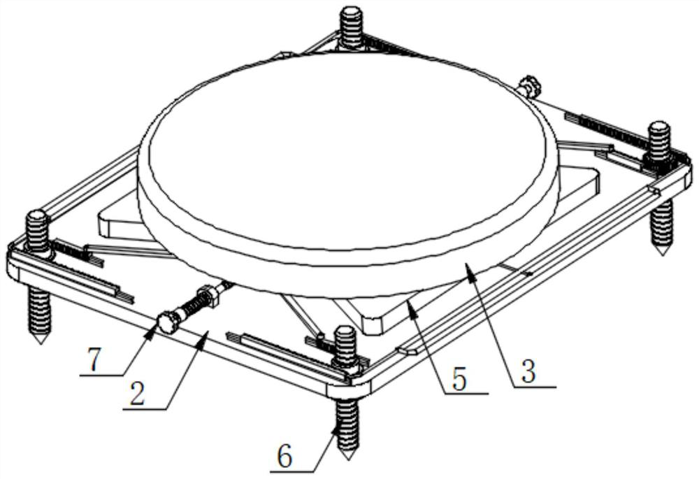
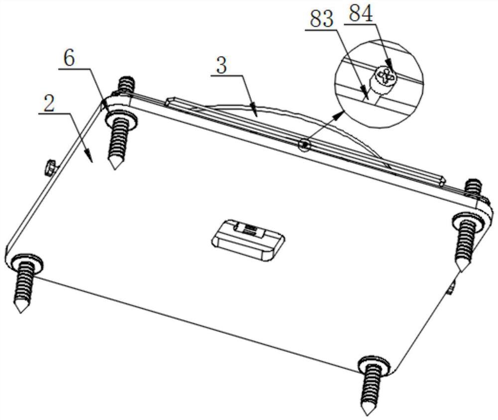
[0033] like Figure 1-9 As shown, the present invention provides a battery-replaceable three-phase cost-controlled smart energy meter, comprising an electric energy meter 1 and a supporting base plate 2, the rear side of the outer surface of the electric energy meter 1 is fixedly connected with the front side of the outer surface of the adjustment structure 3, By setting the adjustment structure 3, and the adjustment structure 3 has t...


PUM


Abstract

The invention discloses a battery-replaceable three-phase charge-control intelligent electric energy meter, and particularly relates to the technical field of three-phase charge-control intelligent electric energy meters, the battery-replaceable three-phase charge-control intelligent electric energy meter comprises an electric energy meter and a supporting bottom plate, and the rear side of the outer surface of the electric energy meter is fixedly connected with the front side of the outer surface of an adjusting structure; the rear side of the outer surface of the adjusting structure is fixedly connected with the front sides of the outer surfaces of two supporting seats, and the rear sides of the outer surfaces of the two supporting seats are fixedly connected with the front side of the outer surface of a supporting bottom plate. Through mutual cooperation of the operation frame, the connecting rods, the first toothed rods and the fixing structure, the operation frame can control the two first toothed rods to move through the two connecting rods, and then the fixing structure can smoothly conduct screw-in installation operation; by means of the arrangement, the multiple fixing structures can be synchronously controlled to achieve positioning installation operation, operation steps are saved, then the installation difficulty is lowered, time is saved, and the purpose of rapid installation and disassembly is achieved.

Description

technical field [0001] The present invention relates to the technical field of three-phase cost-controlled smart energy meters, and more particularly, the present invention relates to a battery-replaceable three-phase cost-controlled smart energy meter. Background technique [0002] A smart energy meter is composed of a measuring unit, a data processing unit, a communication unit, etc., and has functions such as energy measurement, data processing, real-time monitoring, automatic control, and information interaction. Some faults, such as confusion of tariff rates, wrong time of occurrence in event records, failure of anti-theft function, etc., are all caused by clock confusion caused by undervoltage of the clock battery. The traditional single-phase smart energy meter clock battery is usually welded in On the internal circuit board, when the battery is dead, on-site maintenance is more difficult. When replacing the battery, it can only be returned to the factory together wit...

Claims


Application Information

Patent Timeline
Patent Type & Authority Applications(China)
IPC IPC(8): G01R11/04G01R11/02G01R11/24
CPCG01R11/04G01R11/02G01R11/24
Inventor 侯威龙陆睦李洋侍朋赵正飞
Owner 江苏苏源杰瑞科技有限公司
Why Eureka
Try Eureka