
Rotary clamping mechanism for steel bar feeding

A technology of clamping mechanism and steel bars, which can be applied to home appliances, wire fences, and other home appliances. It can solve problems such as difficult alignment of longitudinal bars and unstable steel cages, and achieve reasonable structure and avoid unstable steel cages.

Pending Publication Date: 2022-08-09
中国核工业电机运行技术开发有限公司
View PDF0 Cites 0 Cited by
  • Summary
  • Abstract
  • Description
  • Claims
  • Application Information

AI Technical Summary

Problems solved by technology

[0003] The above-mentioned automatic binding device for reinforcement cages can realize automatic loading of stirrups and automatic binding of reinforcement cages. However, when the stirrups on the stirrup box are short of material, the current stirrup box needs to be removed and replaced with a stirrup. For the stirrup material box full of reinforcement, the end of the longitudinal reinforcement is not fixed at this time, and the reinforcement cage is unstable. It is also difficult to align the longitudinal reinforcement when the stirrup material box is full of material.

Method used


Image

  • Rotary clamping mechanism for steel bar feeding
  • Rotary clamping mechanism for steel bar feeding
  • Rotary clamping mechanism for steel bar feeding

Examples


Embodiment 1

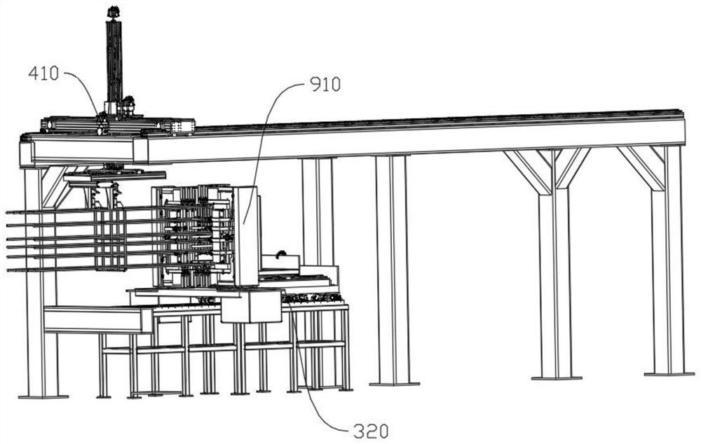
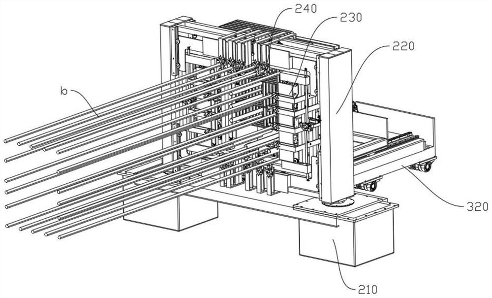
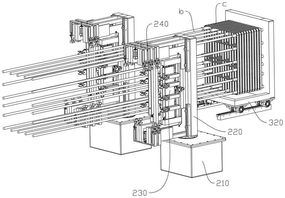
[0029] like Figure 1-8 As shown, the reinforcing bar feeding and rotating clamping mechanism of Embodiment 1 includes a frame, a reinforcing bar cage binding unit, a stirrup box 910 for stacking stirrup groups, and a bearing platform 320 for carrying the stirrup box 910, Both the reinforcement cage binding unit and the bearing platform 320 are connected to the frame, and a number of longitudinal bars are passed through the stirrup material box 910; the reinforcement cage binding unit includes a The stirrups on the box 910 are moved one by one to the stirrup moving assembly 410 at the binding position, and the binding robot for binding the stirrups on the binding position with the longitudinal bars. The stirrup material box 910 and the stirrups move. The assembly 410 and the ligating robot are arranged in sequence along the conveying direction of the longitudinal rib, and further includes a clamping assembly for clamping the longitudinal rib, the clamping assembly is arranged ...

Embodiment 2

[0044] like Figure 9 As shown, Embodiment 2 is based on Embodiment 1, except that there are two groups of moving arm cylinders 251 , the two groups of moving arm cylinders 251 respectively control the movement of the corresponding first four-link 253 , and the two groups of moving arm cylinders 251 are arranged synchronously.

[0045] The difference between the second embodiment and the first embodiment is that when the movable arm 230 needs to move, the two sets of moving arm cylinders 251 need to be activated synchronously and the extension or retraction amount is the same.


PUM


Abstract

The invention discloses a steel bar feeding rotary clamping mechanism which comprises a rack, a steel bar cage binding unit, a stirrup material box used for stacking stirrup sets and a bearing platform used for bearing the stirrup material box, the steel bar cage binding unit and the bearing platform are both connected with the rack, and a plurality of longitudinal bars are arranged in the stirrup material box in a penetrating mode; the reinforcement cage binding unit comprises a stirrup moving assembly used for moving stirrups on a stirrup material box to a binding position one by one and a binding robot used for binding the stirrups on the binding position and longitudinal bars, and further comprises a clamping assembly used for clamping the longitudinal bars, the clamping assembly is arranged on the bearing platform, the clamping assembly and the stirrup material box are arranged adjacently, and the clamping robot is used for clamping the longitudinal bars. The stirrup material box and the clamping assembly are sequentially arranged in the conveying direction of the longitudinal bars. The steel bar feeding rotary clamping mechanism is reasonable in structure, the tail end of a longitudinal bar can be fixed when the stirrup material box is replaced, and instability of a steel bar cage is avoided.

Description

technical field [0001] The invention relates to a clamping mechanism, in particular to a rotating clamping mechanism for feeding steel bars. Background technique [0002] In the prior art, the automatic binding device for steel cages includes a frame, a binding unit for steel cages connected to the frame, and a stirrup material box for stacking stirrup groups, and several longitudinal bars pass through the stirrup material. The reinforcement cage binding unit includes a stirrup moving assembly for moving the stirrups on the stirrup material box to the binding position one by one, and a stirrup moving assembly for moving the stirrups on the binding position to the longitudinal reinforcement. In the binding robot for binding, the stirrup material box, the stirrup moving assembly and the binding robot are arranged in sequence along the conveying direction of the longitudinal bars. [0003] The above-mentioned automatic binding device for steel cages can realize automatic feedi...

Claims


Application Information

Patent Timeline
Patent Type & Authority Applications(China)
IPC IPC(8): B21F23/00B21F29/00
CPCB21F23/00B21F29/00
Inventor 高飞刘艳霞刘世辉
Owner 中国核工业电机运行技术开发有限公司
Learn More