Automatic efficient spring manufacturing process and production line

A production process and high-efficiency technology, applied in the direction of manufacturing tools, wire-made springs, other manufacturing equipment/tools, etc., can solve the problems of inability to assemble the whole process, low degree of automation, time-consuming and labor-intensive, etc., to reduce manual participation, reduce The effect of assembly and weld strength

Pending Publication Date: 2022-08-09
浙江三和弹簧有限公司
View PDF14 Cites 0 Cited by
  • Summary
  • Abstract
  • Description
  • Claims
  • Application Information

AI Technical Summary

Problems solved by technology

CN202011202451.5 A tooling fixture for spring assembly and its use method, including a clamping mechanism and an assembly mechanism, the clamping mechanism includes symmetrically arranged fixing plates, each of which is provided with clamping blocks, A placing plate is arranged between the clamping blocks, a first fixing block and a second fixing block are arranged on both sides of the fixing plate, a first limiting device is arranged on the first fixing block, and a first limiting device is arranged on the second fixing block. A second limiting device is provided on the block, and a moving device is provided between one of the fixed plates and the clamping block; its structure is poor in practicability and cannot be assembled in the whole process
[0003] The existing spring needs to be assembled by pulling the spring wire, shaping it, heat treating it, and then winding it. The degree of automation is low, because the accuracy of the assembly needs to be controlled by experience due to human participation, and the technical requirements for people relatively high
Long-term training is required for welding and assembly personnel before they can engage in operation, which is time-consuming and labor-intensive
[0004] CN201911152142.9 A supporting spring and its manufacturing method. Although it provides a manufacturing method, its degree of automation is unreasonable in the design of the spring pulling connection part, which is prone to pulling deformation

Method used


Image

  • Automatic efficient spring manufacturing process and production line
  • Automatic efficient spring manufacturing process and production line
  • Automatic efficient spring manufacturing process and production line

Examples


Embodiment Construction

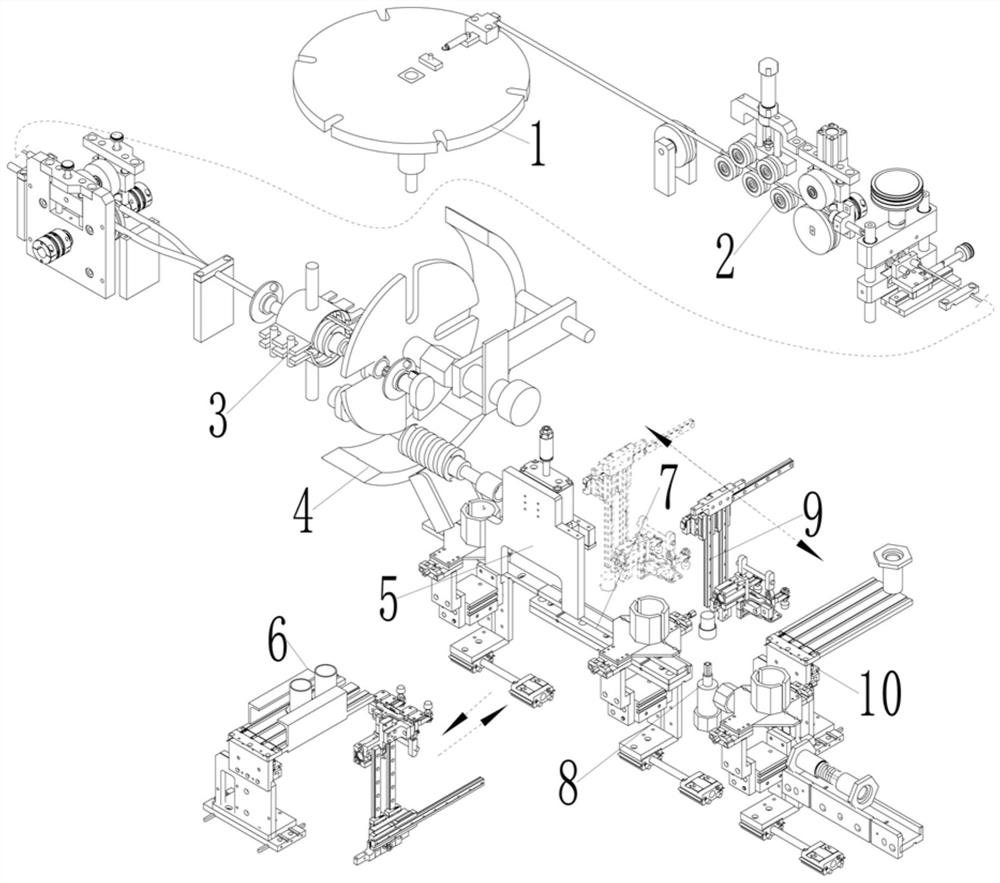
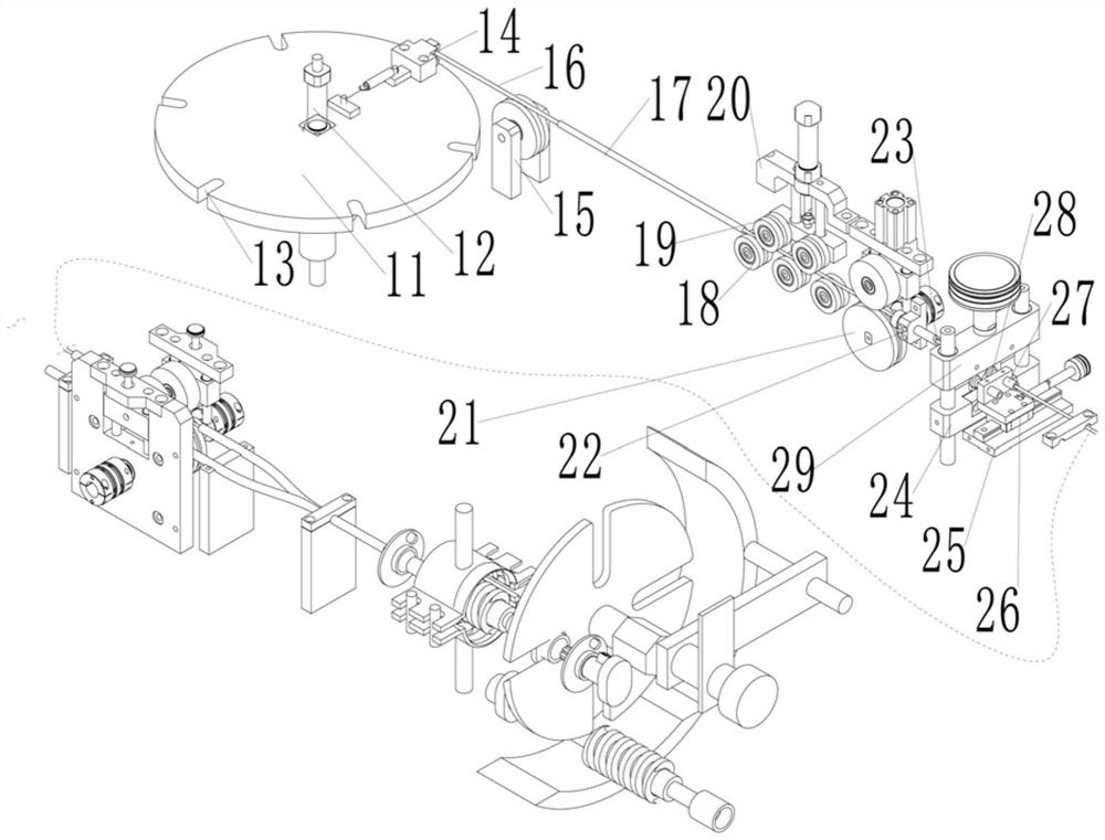
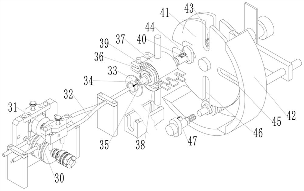
[0043] like Figure 1-6 As shown, in the spring product of this embodiment, the spring product 61 includes a helical shaped spring 62; the shaped spring 62 has two ends, and a first end cap 63 and a second end cap are respectively connected to the two ends of the shaped spring 62 end cap 64;

[0044] The first end cap 63 and / or the second end cap 64 has a hollow hole and a connecting flange; the hollow hole is welded to the end of the formed spring 62, and the connecting flange is used to connect the corresponding pulling member.

[0045] In the production line for automatic and efficient production of springs in this embodiment, the produced spring products 61 include a helical shaped spring 62; second end cap 64;

[0046] The first end cap 63 and / or the second end cap 64 have a hollow hole and a connecting flange; the hollow hole is welded to the end of the formed spring 62, and the connecting flange is used to connect the corresponding pulling member;

[0047] A blocking...


PUM


Abstract

The invention relates to an automatic efficient spring manufacturing process. A spring product (61) comprises a spiral formed spring (62). The forming spring (62) is provided with two end heads, and the two end heads of the forming spring (62) are connected with a first end cap (63) and a second end cap (64) respectively. The first end cap (63) and/or the second end cap (64) is provided with a hollow hole and a connecting flange; the hollow hole is in welded connection with the end of the forming spring (62), and the connecting flange is used for being connected with a corresponding traction piece; the device is reasonable in design, compact in structure and convenient to use.

Description

technical field [0001] The invention relates to an automatic and efficient manufacturing process of a spring. Background technique [0002] After the spring products of the existing equipment are assembled, manual processing is required. How to realize the automation of the subsequent production of the spring has become a technical problem that needs to be solved urgently. CN202011202451.5 A tooling fixture for spring assembly and a method of using the same, including a clamping mechanism and an assembling mechanism, the clamping mechanism includes symmetrically arranged fixing plates, each of the fixing plates is provided with a clamping block, A placing plate is arranged between the clamping blocks, a first fixing block and a second fixing block are also arranged on both sides of the fixing plate, a first limiting device is arranged on the first fixing block, and the second fixing A second limiting device is arranged on the block, and a moving device is arranged between o...

Claims


Application Information

Patent Timeline
Patent Type & Authority Applications(China)
IPC IPC(8): B23P15/00B23P23/06B21F35/00B21F3/02
CPCB23P15/00B23P23/06B21F35/00B21F3/02
Inventor 李云静施遨翔周文成叶隆
Owner 浙江三和弹簧有限公司
Why Eureka
Try Eureka