
Transportation tool for mold forming

A transportation tool and mold forming technology, which is applied in the direction of transportation and packaging, anti-rot containers, external accessories, etc., can solve the inconvenience of improving the moisture-proof effect of mold transportation, the shock-absorbing stability effect of the inconvenient device structure, and the inconvenient device for wind shielding Problems such as rain-proof effect, to achieve the effect of ensuring stability, improving moisture resistance, and improving stability and safety

Pending Publication Date: 2022-08-09
SUZHOU QINDE METAL
View PDF7 Cites 0 Cited by
  • Summary
  • Abstract
  • Description
  • Claims
  • Application Information

AI Technical Summary

Problems solved by technology

[0005] In order to make up for the deficiencies of the existing technology, it solves the shock-absorbing stability effect that is not convenient for the transportation of the lifting device structure, the moisture-proof effect of the transportation of the mould, the heat dissipation effect of the lifting device structure, and the wind shielding effect of the lifting device. The problem of rain protection effect

Method used


Image

  • Transportation tool for mold forming
  • Transportation tool for mold forming
  • Transportation tool for mold forming

Examples


Embodiment 1

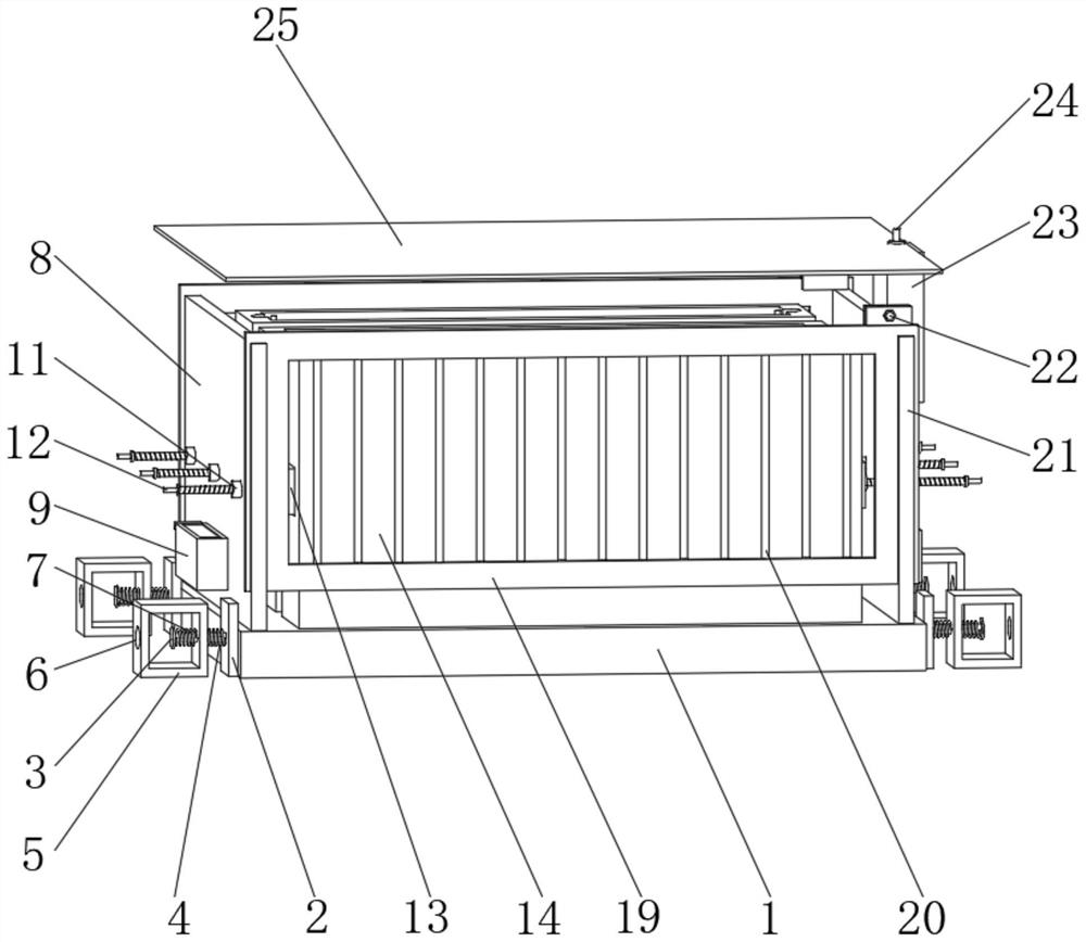
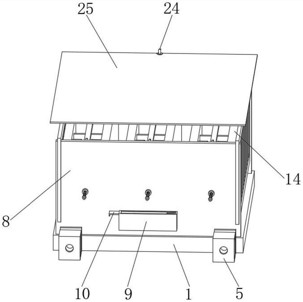
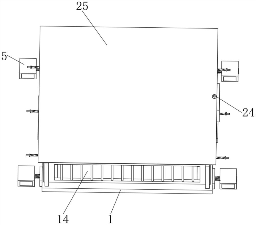
[0027] see Figure 1-3 As shown, a transportation tool for mold forming includes a bottom plate 1 and a first vertical plate 8, the side of the bottom plate 1 is provided with a connecting plate 2, and the middle position of the connecting plate 2 is connected with a connecting rod 3, and the connecting rod 3 A first spring 4 is arranged on the outer side of the cable, an installation frame 5 is arranged at the end of the first spring 4, and an installation hole 6 is opened on the inner side of the installation frame 5, and a second spring 7 is arranged at the end of the connecting rod 3.

[0028] The installation frame 5 constitutes an elastic structure by the first spring 4, the second spring 7 and the connecting rod 3, and the connecting rod 3 and the connecting plate 2 are vertically integrated, and the connecting plate 2, the connecting rod 3, the first spring 4 , The installation frame 5, the installation hole 6, and the second spring 7 are symmetrically arranged in two ...

Embodiment 2

[0030] see Figure 1-5 As shown, Comparative Example 1, as another embodiment of the present invention, the first vertical plate 8 is arranged on the top of the bottom plate 1, and the outer wall of the first vertical plate 8 is provided with a moisture-proof box 9, and the inner side of the moisture-proof box 9 A sealing plate 10 is provided, a threaded pipe 11 penetrates through the inner side of the first vertical plate 8, and a threaded rod 12 penetrates through the inner side of the threaded pipe 11. A placing box 14 is provided, the inner side of the placing box 14 is provided with an isolation plate 15, and the top of the isolation plate 15 is provided with a top plate 16, the end of the top plate 16 is provided with a fixing bolt 17, and the bottom end of the fixing bolt 17 is provided with a fixing plate 18. The side of the first vertical plate 8 is provided with a protective plate 19, and the inner side of the protective plate 19 is provided with a protective rod 20,...


PUM


Abstract

The invention belongs to the field of transport tools, and particularly relates to a transport tool for mold forming, which comprises a bottom plate and a first vertical plate, the side of the bottom plate is provided with a connecting plate, the middle position of the connecting plate is connected with a connecting rod, the outer side of the connecting rod is provided with a first spring, and the end part of the first spring is provided with a mounting frame; a mounting hole is formed in the inner side of the mounting frame, a second spring is arranged at the end of the connecting rod, the first vertical plate is arranged at the top of the bottom plate, a damp-proof box is arranged on the outer wall of the first vertical plate, a sealing plate is arranged on the inner side of the damp-proof box, a threaded pipe penetrates through the inner side of the first vertical plate, and a threaded rod penetrates through the inner side of the threaded pipe; an abutting plate is arranged at the end of the threaded rod. According to the device, the damping stability effect of transportation of the device structure is improved conveniently, the transportation moisture-proof effect of a mold is improved conveniently, the heat dissipation effect of the device structure is improved conveniently, and the wind shielding and rain shielding effects of the device are improved conveniently.

Description

technical field [0001] The invention relates to the field of transportation tools, in particular to a transportation tool for mold forming. Background technique [0002] The means of transport refer to locomotives, passenger and freight vehicles, automobiles, ships, and airplanes that complete the transportation of passengers and goods. Since these means of transport are tools for completing the displacement of passengers and goods, they are also called transportation mobile devices. According to the degree of independence they are engaged in transportation activities, they can be divided into three categories: those that do not load passenger and cargo containers and only provide motive power, such as locomotives, carts (tugboats), tractors, etc.; Driven means of transport, such as vehicles, trailers, barges, etc.; independent means of transport, such as ships, cars, planes, etc. [0003] The traditional means of transportation have the effect of shock absorption and stab...

Claims


Application Information

Patent Timeline
Patent Type & Authority Applications(China)
IPC IPC(8): B65D25/10B65D81/02B65D81/26B65D25/04B65D25/20
CPCB65D25/10B65D81/02B65D81/266B65D25/04B65D25/20
Inventor 苏春洲
Owner SUZHOU QINDE METAL
Learn More