Light storage and charging control system and method

A technology of control system and control method, which is applied in the field of power electronics, can solve the problems of complicated and cumbersome grid connection, waste of manpower and material resources, etc., and achieve the effect of avoiding short circuit of power supply and waste of manpower and material resources

Pending Publication Date: 2022-08-09
绿能慧充数字技术有限公司
0 Cites 0 Cited by

AI-Extracted Technical Summary

Problems solved by technology

[0004] The purpose of the present invention is to provide a solar storage charging control system and method to solve the technical problem...

Abstract

The invention belongs to the technical field of power electronics, and particularly relates to an optical storage and charging control system and method. Comprising a grid-connected point E and a main control module, and the grid-connected point E is connected with a node D through a first air circuit breaker QF1; the node D is connected with the node B through a third alternating current contactor KM3; the node B is connected with the energy storage converter; the energy storage converter is connected with the photovoltaic energy storage module; the grid-connected point E is connected with the node C through a second air circuit breaker QF2 and a first alternating current contactor KM1 which are sequentially connected in series; the node C is connected with the node B through a second alternating current contactor KM2; the node C is connected with a load through a third air circuit breaker QF3; the first alternating current contactor KM1 and the second alternating current contactor KM2 are interlocked, and the second alternating current contactor KM2 and the third alternating current contactor KM3 are interlocked; and the main control module is used for acquiring the forward active power data of the grid-connected point E and controlling the output power of the energy storage converter according to the forward active power data. Through the interlocking relation between the alternating current contactors, power supply short circuit caused by sudden power supply of a power grid is avoided.

Application Domain

Technology Topic

Image

  • Light storage and charging control system and method
  • Light storage and charging control system and method

Examples

  • Experimental program(2)

Example Embodiment

[0043] Example 1
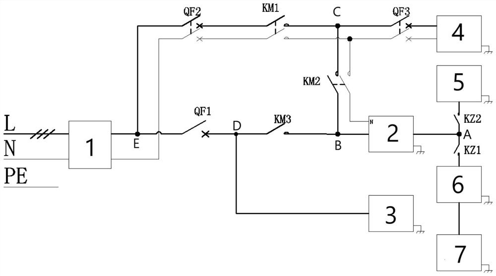
[0044] like Figure 1-2 As shown, an optical storage and charging control system includes a grid connection point E and a main control module, and the grid connection point E is connected to the node D through the first air circuit breaker QF1;
[0045] The node D is connected to the charging module 3, and the node D is connected to the node B through the third AC contactor KM3;
[0046] Node B is connected to the energy storage converter 2;
[0047] The energy storage converter 2 is connected to node A;
[0048] Node A is connected to the DC-DC module 6 through the first DC contactor KZ1, and the DC-DC module 6 is connected to the photovoltaic string 7;
[0049] Node A is connected to the energy storage battery 5 through the second DC contactor KZ2;
[0050] The grid connection point E is connected to the node C through the second air circuit breaker QF2 and the first AC contactor KM1 connected in series in sequence;
[0051] Node C is connected to Node B through the second AC contactor KM2;
[0052] The node C is connected to the load 4 through the third air circuit breaker QF3;
[0053] The first AC contactor KM1 is interlocked with the second AC contactor KM2, and the second AC contactor KM2 is interlocked with the third AC contactor KM3;
[0054] There is a two-way meter 1 at the grid connection point E;
[0055] The signal input end of the main control module is connected to the bidirectional meter 1 , and the signal output end of the main control module is connected to the energy storage converter 2 .
[0056] DI1, DI2, DI3, DI4 and DI5 of the main control module are respectively connected with the feedback contact of the first AC contactor KM1, the feedback contact of the second AC contactor KM2, the feedback contact of the third AC contactor KM3, the first AC contactor KM1 The feedback contact of the DC contactor KZ1 is connected with the feedback contact of the second DC contactor KZ2;
[0057]DO1, DO2, DO3, DO4 and DO5 of the main control module respectively correspond to the coil control state of the first AC contactor KM1, the coil control state of the second AC contactor KM2, the coil control state of the third AC contactor KM3, the first The coil control state of the DC contactor KZ1 and the coil control state of the second DC contactor KZ2;
[0058] Check whether the control of the first AC contactor KM1, the second AC contactor KM2, the third AC contactor KM3, the first DC contactor KZ1 and the second DC contactor KZ2 is effective through the DI and DO of the main control module.
[0059] RS85 interface is used for communication between the main control module and the two-wire meter;
[0060] The main control module and the energy storage converter 2 communicate through CAN;
[0061] The main control module and the charging module 3 also communicate through CAN.
[0062] This system can control the opening and closing of the contactor to achieve the following functions:
[0063] The grid supplies power to the load 4;
[0064] The power grid charges the electric vehicle through the charging module 3 or the energy storage converter 2;
[0065] The power grid charges the energy storage battery 5 through the energy storage converter 2;
[0066] The photovoltaic string 7 charges the energy storage battery 5 through the DC-DC module 6;
[0067] The photovoltaic string 7 charges the electric vehicle through the DC-DC module 6;
[0068] The photovoltaic string 7 supplies power to the load 4 through the DC-DC module 6 and the energy storage converter 2;
[0069] The energy storage battery 5 supplies power to the load 4 through the energy storage converter 2;
[0070] The energy storage battery 5 charges the electric vehicle through the energy storage converter 2 and the charging module 3 .

Example Embodiment

[0071] Example 2
[0072] A method for controlling light storage and charging, comprising the following steps:
[0073] The forward active power data obtained from the grid is detected by the two-wire meter and sent to the main control module;
[0074] When there is electricity in the grid, the energy storage battery 5 and the photovoltaic string 7 are connected to the grid or absorbed by the energy storage converter 2, and the main control module controls the inverter output power of the energy storage converter 2 according to the forward active power data. ;
[0075] When the power grid is powered off, the energy storage battery 5 and the photovoltaic string 7 supply power to the load 4 through the off-grid inverter 2 through the energy storage converter 2;
[0076] When the power grid is switched from power on to power off, the first AC contactor KM1 and the third AC contactor KM3 are disconnected first, and the second AC contactor KM2 is pulled in after 2S, and the energy storage converter 2 is started synchronously for off-grid Inverter output;
[0077] When the power grid goes from power failure to power, first disconnect the second AC contactor KM2, synchronously stop the off-grid inverter output of the energy storage converter, and pull in the first AC contactor KM1 and the third AC contactor KM3 after 2S .
[0078] When the inverter output power of the energy storage converter 2 is controlled according to the forward active power data, in order to avoid the violation of the surplus power grid caused by the power of the load 4 being less than the output power of the energy storage converter 2, the two-way meter 1 can be used to measure the secondary The power obtained by the grid is the forward active power for monitoring, and a judgment threshold is set at the same time. When the forward active power is less than the judgment threshold, the grid-connected inverter output of the energy storage converter 2 is stopped, and the judgment threshold is less than the rated value of the energy storage converter. Output power; specifically includes the following steps:
[0079] If the forward active power is greater than the rated output power of the energy storage converter + the judgment threshold, the main control module controls the full power inverter output of the energy storage converter 2;
[0080] If the judgment threshold < forward active power < rated output power of the energy storage converter, the main control module controls the inverter output of the energy storage converter 2 to be: forward active power - judgment threshold;
[0081] If the forward active power is less than the judgment threshold, the energy storage converter 2 stops the inverter output.
[0082] The size of the judgment threshold is 3 kW.

PUM

no PUM

Description & Claims & Application Information

We can also present the details of the Description, Claims and Application information to help users get a comprehensive understanding of the technical details of the patent, such as background art, summary of invention, brief description of drawings, description of embodiments, and other original content. On the other hand, users can also determine the specific scope of protection of the technology through the list of claims; as well as understand the changes in the life cycle of the technology with the presentation of the patent timeline. Login to view more.

Similar technology patents

Substation perimeter laser fence position correction system and method based on image capture

ActiveCN109523761AHigh precisionAvoid wasting manpower and material resourcesFencingBurglar alarm by disturbance/breaking stretched cords/wiresImage basedImage capture
Owner:SHANGHAI UNIVERSITY OF ELECTRIC POWER

JP electrical cabinet temperature monitoring system

PendingCN113865712AAvoid wasting manpower and material resourcesImprove efficiency and accuracyImage enhancementRadiation pyrometryEngineeringMonitoring site
Owner:STATE GRID ANHUI ELECTRIC POWER CO LTD ANQING POWER SUPPLY CO +1

Interlayer alignment visual monitoring method

InactiveCN112165854AAvoid wasting manpower and material resourcesLow costElectrical componentsEngineeringMaterial resources
Owner:YIXING SILICON VALLEY ELECTRONICS TECH

Variable-speed pumped storage unit rotor short circuit and eccentricity fault diagnosis method

PendingCN114492597AAvoid wasting manpower and material resourcesElectric winding testingCharacter and pattern recognitionNetwork modelRotor eccentricity
Owner:HUAZHONG UNIV OF SCI & TECH

Video image acquisition system

InactiveCN104394388AAvoid wasting manpower and material resourcesClosed circuit television systemsMaterial resourcesStern
Owner:重庆长航东风船舶工业有限公司

Classification and recommendation of technical efficacy words

  • Avoid shorting the power supply
  • Avoid wasting manpower and material resources

Comprehensive controller and control method for sunlight greenhouse electric film rolling machine

ActiveCN105900745AAvoid shorting the power supplyThe regulation process is stableClimate change adaptationGreenhouse cultivationAutomatic controlControl mode
Owner:SHANDONG AGRICULTURAL UNIVERSITY

Intelligent building management and control system

InactiveCN109459994AReduce lossesAvoid wasting manpower and material resourcesProgramme total factory controlData informationElectricity
Owner:安徽圆舟率创新科技有限公司

Software testing method and device

ActiveCN109871328AAvoid wasting manpower and material resourcesReduce workloadSoftware testing/debuggingTesting softwareMaterial resources
Owner:CHINANETCENT TECH

Sorting method for chips with inappropriate yield to technological level

ActiveCN104752259AAvoid wasting manpower and material resourcesImprove efficiencySemiconductor/solid-state device manufacturingLower yieldPersonalization
Owner:SEMICON MFG INT (SHANGHAI) CORP

IC-card intelligent electric meter field fault diagnosis and solution method

ActiveCN105321265ASolve electricity problemsAvoid wasting manpower and material resourcesApparatus for hiring articlesEmbedded systemMaterial resources
Owner:STATE GRID ANHUI ELECTRIC POWER +1
Why Eureka
Try Eureka