Demagnetizer using biplane demagnetizing effect

A demagnetization device, a plane technology, applied in the direction of electric alarms, alarms relying on moving hand-held items, near-field transmission systems using transceivers, etc., can solve problems such as false alarms in EAS systems

Inactive Publication Date: 2004-05-12
SENSORMATIC ELECTRONICS CORP
View PDF2 Cites 0 Cited by
  • Summary
  • Abstract
  • Description
  • Claims
  • Application Information

AI Technical Summary

Problems solved by technology

This can cause unwanted false alarms of the EAS system

Method used


Image

  • Demagnetizer using biplane demagnetizing effect
  • Demagnetizer using biplane demagnetizing effect
  • Demagnetizer using biplane demagnetizing effect

Examples


Embodiment Construction

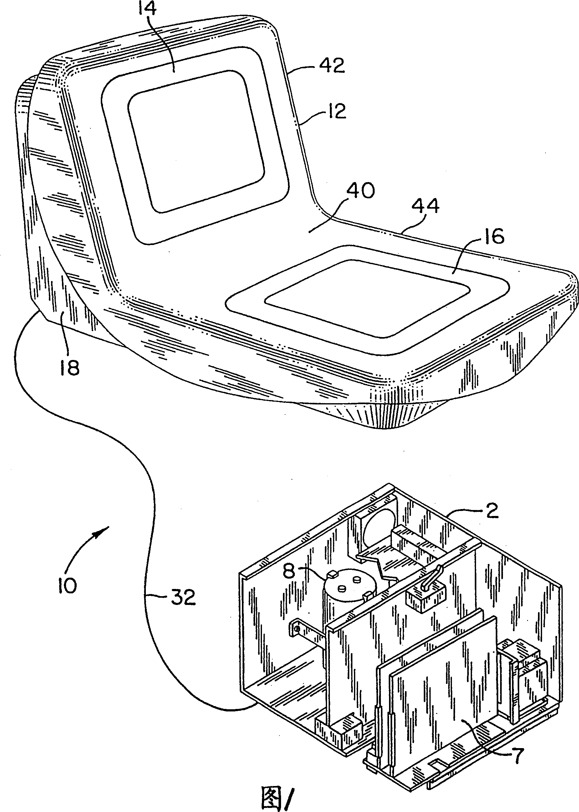
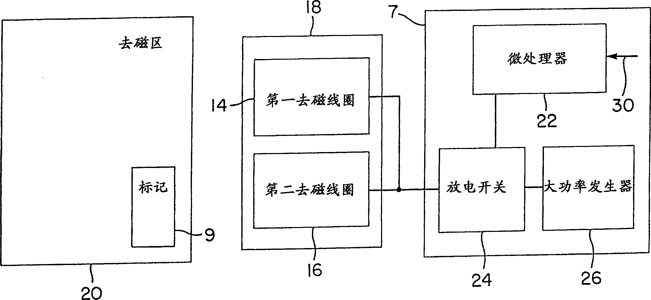
[0026] As shown in FIG. 1 , the demagnetization device 10 of the present invention is used to demagnetize the EAS markers used in the EAS system. The demagnetization device 10 can demagnetize the EAS mark by increasing the range or area of ​​the entire demagnetization region where the mark can be demagnetized. The demagnetization device 10 can also demagnetize the EAS marks located in different directions in the demagnetization area.

[0027] As shown in FIG. 1 , the demagnetization device 10 of the present invention includes a demagnetization unit 12 and an excitation or power supply unit 2 . The degaussing unit 12 includes first and second coil portions which respectively form a first degaussing coil 14 and a second degaussing coil 16 located within a housing 18 . The housing 18 has a cavity 40 formed by sides 42 and a bottom 44 . The first and second degaussing coils 14 and 16 are shown to have a square configuration and are positioned respectively in the sides 42 and bot...


PUM


Abstract

A deactivation device for use in deactivating electronic article surveillance ('EAS') tags includes a deactivating coil having first and second coil parts. The first coil part is positioned in angular adjacent relation to the second coil part so that the coil parts are adapted to transmit simultaneously a deactivating field. The deactivating field forms a deactivation zone having a configuration which permits for deactivation of an active EAS tag when the active EAS tag is situated within the deactivation zone.

Description

technical field [0001] The present invention relates generally to degaussing devices for use in electronic article surveillance ("EAS") systems, and more particularly to degaussing devices that utilize biplane degaussing to degauss EAS tags or tags used in EAS systems. Background technique [0002] In the current EAS system, an EAS mark or label is placed on the item, and if an unauthorized attempt is made to take an item with a valid EAS mark, it can be detected by the EAS system. One type of EAS marker comprises a length of amorphous magnetic material disposed substantially parallel to a length of magnetizable material serving as a control element. When a valid marker, ie a marker having a magnetized control element, is placed in an alternating magnetic field defining an interrogation zone, the marker produces a detectable valid marker signal. When a marker is deactivated by demagnetizing its control element, the marker no longer produces a detectable marker signal. Such...

Claims


Application Information

Patent Timeline
Patent Type & Authority Patents(China)
IPC IPC(8): G08B13/24H01Q7/00H04B5/02
CPCG08B13/242
Inventor 韦恩·H·马丁
Owner SENSORMATIC ELECTRONICS CORP
Why Eureka
Try Eureka