Glittering cube-corner retroreflective sheeting

A retro-reflective, cube-based technology, used in optics, optical components, thin material processing, etc.

Inactive Publication Date: 2004-05-19
3M CO
View PDF57 Cites 1 Cited by
  • Summary
  • Abstract
  • Description
  • Claims
  • Application Information

AI Technical Summary

Problems solved by technology

Although the currently known technologies are very effective in improving the conspicuousness of retroreflective sheeting during the d

Method used


Image

  • Glittering cube-corner retroreflective sheeting
  • Glittering cube-corner retroreflective sheeting
  • Glittering cube-corner retroreflective sheeting

Examples


Embodiment 1a-1e

[0162] Examples 1a-1ee... Batch Production of Glitter Articles

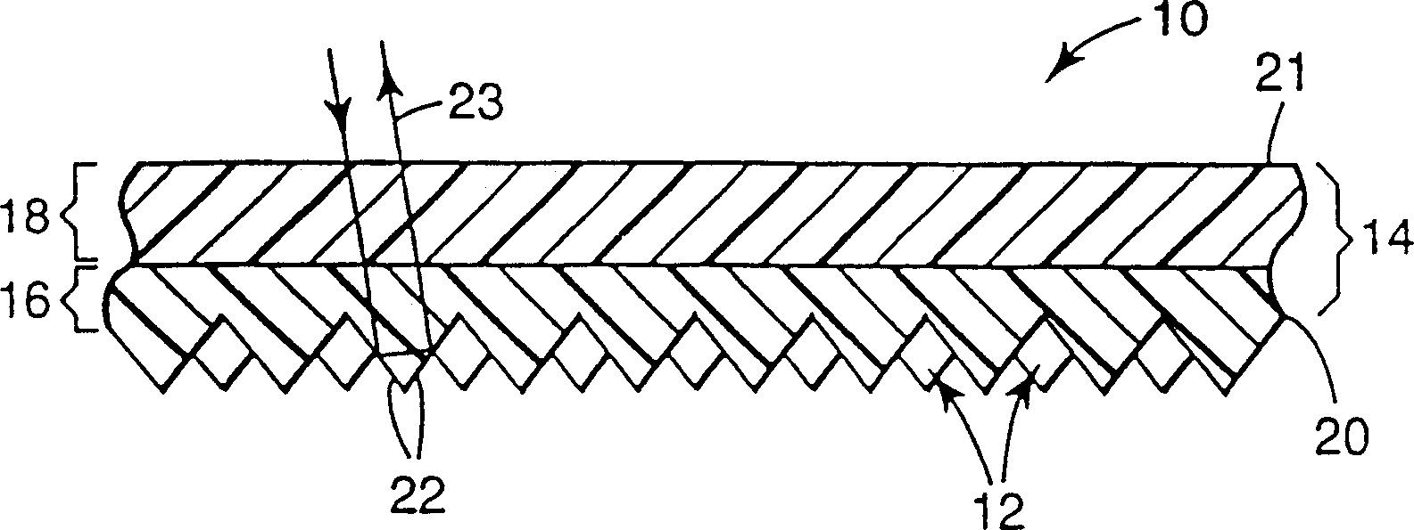
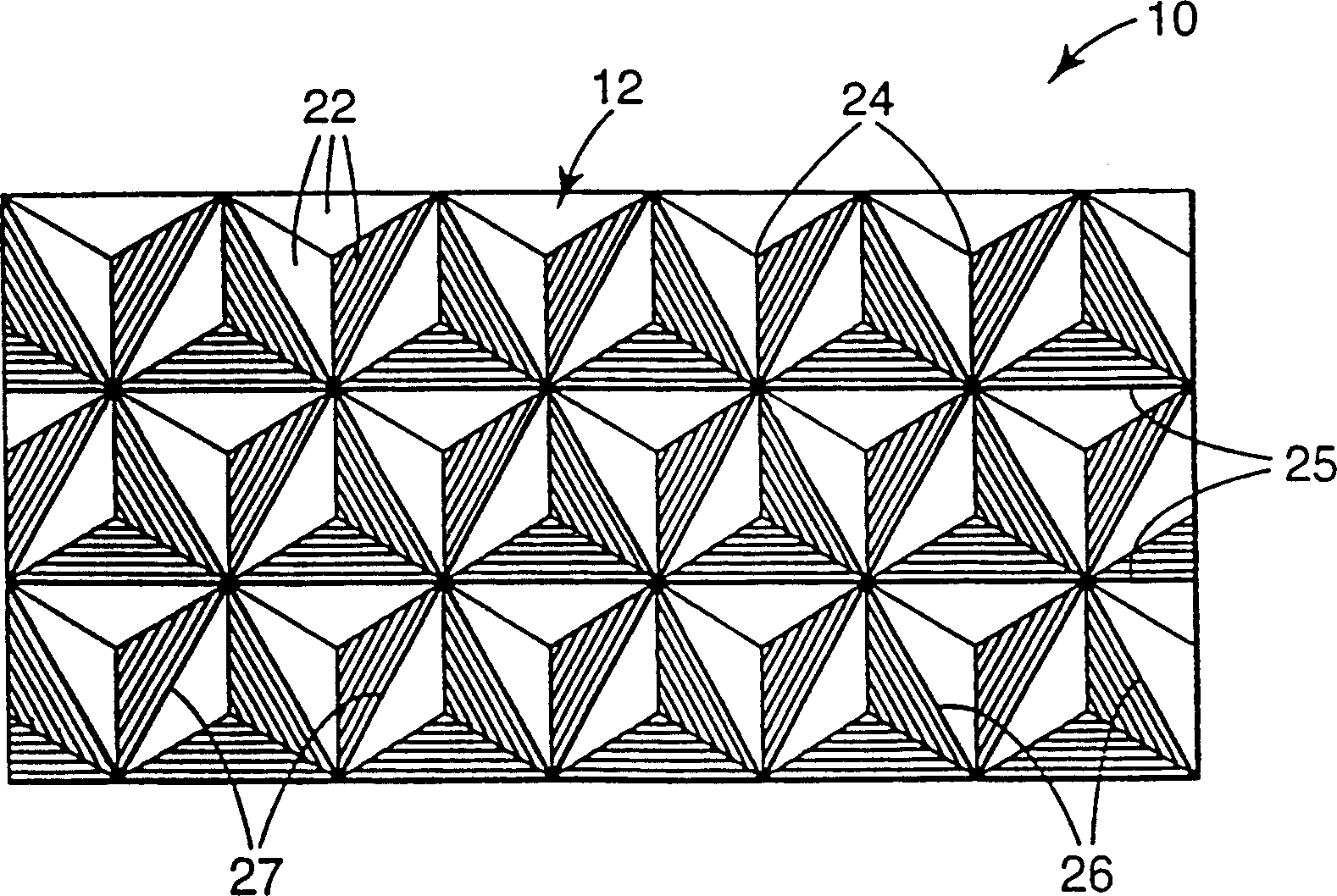
[0163] Ordered cube-corner retroreflective sheeting was prepared as described in Example 1 of US Patent Application Serial No. 08 / 472,444, filed June 7,1995. The retroreflective sheeting comprises cube-corner retroreflective elements, a 0.01 inch (250 micron) thick colorless, transparent, flexible body layer and a 0.002 inch (50 micron) thick polyethylene terephthalate carrier film, wherein the The cube-corner elements are approximately 0.0035 inches (90 microns) from apex to base and are made of 1,6-hexanediol diacrylate, trimethylolpropane triacrylate, and bisphenol A epoxy diacrylate at 25: 50:25 weight ratio and using 1% resin weight Darocur TM 4265 as a photoinitiator. The resin was cured through the film using a FUSION H lamp (available from Fusion UV Curing systems, Inc. (Gaithersburg, Maryland)) at 235 W / cm, 25 ft / min (7.6 m / min) Post-curing was accomplished from the backside of the cube-corner elem...

Embodiment 1

[0164] Example 1s was used to test lightness, and this sample exhibited an LFY value of 37.73.

[0165] serial number

Embodiment 2a-2

[0166] Examples 2a-2m...Imaged Glittering Articles Formed Using Flexographic Printing Plates

[0167] Ordered cube-corner retroreflective sheeting as described in Examples 1a through 1ee was used. Place a sheet of Kraft release paper on the rubber mat of a Hix Model N800 thermal laminator. There will be raised images ( Figure 16a ) is placed on top of the paper with the image of the letters "JPJ" surrounded by a circle. An ordered cube-corner retroreflective sheeting with a polyester carrier on top of the body layer was placed on top of the flexographic printing plate such that the backside of the cube-corner elements contacted the raised image elements on the printing plate. Place a second sheet of Kraft release paper on top of the cube-corner sheet. This arrangement is equivalent to Figure 11 , where the flexographic printing plate is represented by 104. Heat this assembly to 350°F (175°C). The air line pressure (psi) and heating time are listed in Table 2. At the ...


PUM

PropertyMeasurementUnit
Heightaaaaaaaaaa

Abstract

A cube-corner retroreflective sheeting (60) includes an array of cube-corner elements (30) that are defined by three sets of intersecting parallel grooves (45, 46, 47). The cube-corner elements (30) are arranged in the array such that the sheeting (60) glitters when exposed to light. The glitter is in the form of many discrete points of light (68) that tend to blink on and off when viewed by the nacked eye. The array may be configured such that a dihedral angle alpha varies between adjacent cube faces (31) of adjacent cube-corner elements (30) in each groove in one of the groove sets (45, 46 or 47) and such that base planes (36) are not parallel to each other when the sheeting (60) is laid flat. Preferably, the dihedral angle alpha between faces (31) of adjacent cube-corner elements (30) varies in essentially all of the grooves such that the cube-corner elements are randomly tilted throughout the array. The sheeting glitters very well under daytime viewing conditions and also to some extent under nighttime or retroreflective conditions. The glittering effect can enhance the sheeting's conspicuity, and hence highlight a person's presence to give them improved safety and security.

Description

technical field [0001] The present invention relates to a cube-corner retroreflective sheeting that shimmers when exposed to light. Background technique [0002] Retroreflective sheeting is characterized by its ability to reflect a large amount of incident light back to the light source. This unique capability has driven the widespread use of retroreflective sheeting on signs, barricades, traffic cones, clothing, and other items that are required to be seen at night. The retroreflective sheeting will enhance the visibility of the retroreflective sheeted article, especially at night. [0003] Very common retroreflective sheeting utilizes an array of cube-corner elements to reflect light. Figures 1 and 2 illustrate examples of such retroreflective sheeting, generally indicated by the numeral 10 . The array of cube-corner elements 12 projects from a first (i.e., back) side of a body portion 14, which includes a body layer 18 (also referred to in the art as a cover layer), an...

Claims


Application Information

Patent Timeline
IPC IPC(8): G02B5/124
CPCY10T428/24479G02B5/124
Inventor 吉尼恩·M·舒斯塔保罗·E·马瑞克麦斯欧·R·C·阿特金森查瑞·M·福瑞小奥斯特·本森
Owner 3M CO
Why Eureka
Try Eureka