Microwave oven

A microwave and microwave technology, applied in the field of microwave ovens, can solve the problems of low temperature, uneven heat distribution, and inability to transmit heat.

Inactive Publication Date: 2004-06-02
LG ELECTRONICS INC
View PDF0 Cites 0 Cited by
  • Summary
  • Abstract
  • Description
  • Claims
  • Application Information

AI Technical Summary

Problems solved by technology

[0016] However, in the above-mentioned convection cooking microwave oven, due to the distance between the heater 18 and the food, the non-uniformity of heat distribution makes it difficult to control the temperature inside the cooking chamber, and the temperature of the portion adjacent to the heater 18 is higher, and The opposite wall temperature of the heater 18 is lower
In order to make the heat distribution uniform, a fan 23 is installed on the side of the heater, but the circulating air flow interferes with the heat flow generated by the heater 18, so the heat cannot be normally transmitted to the opposite wall inside the cooking chamber 2a
[0017] In addition, for a conventional grill cooking microwave oven, uneven heat distribution may occur due to the distance between the heater and the food piece, and since it only uses convective heat transfer with a limited surface temperature of 600°C, it takes a long time to make the cooking sufficient temperature inside the chamber

Method used


Image

  • Microwave oven
  • Microwave oven
  • Microwave oven

Examples


Embodiment Construction

[0031] Preferred embodiments of the present invention are described in detail with reference to the accompanying drawings.

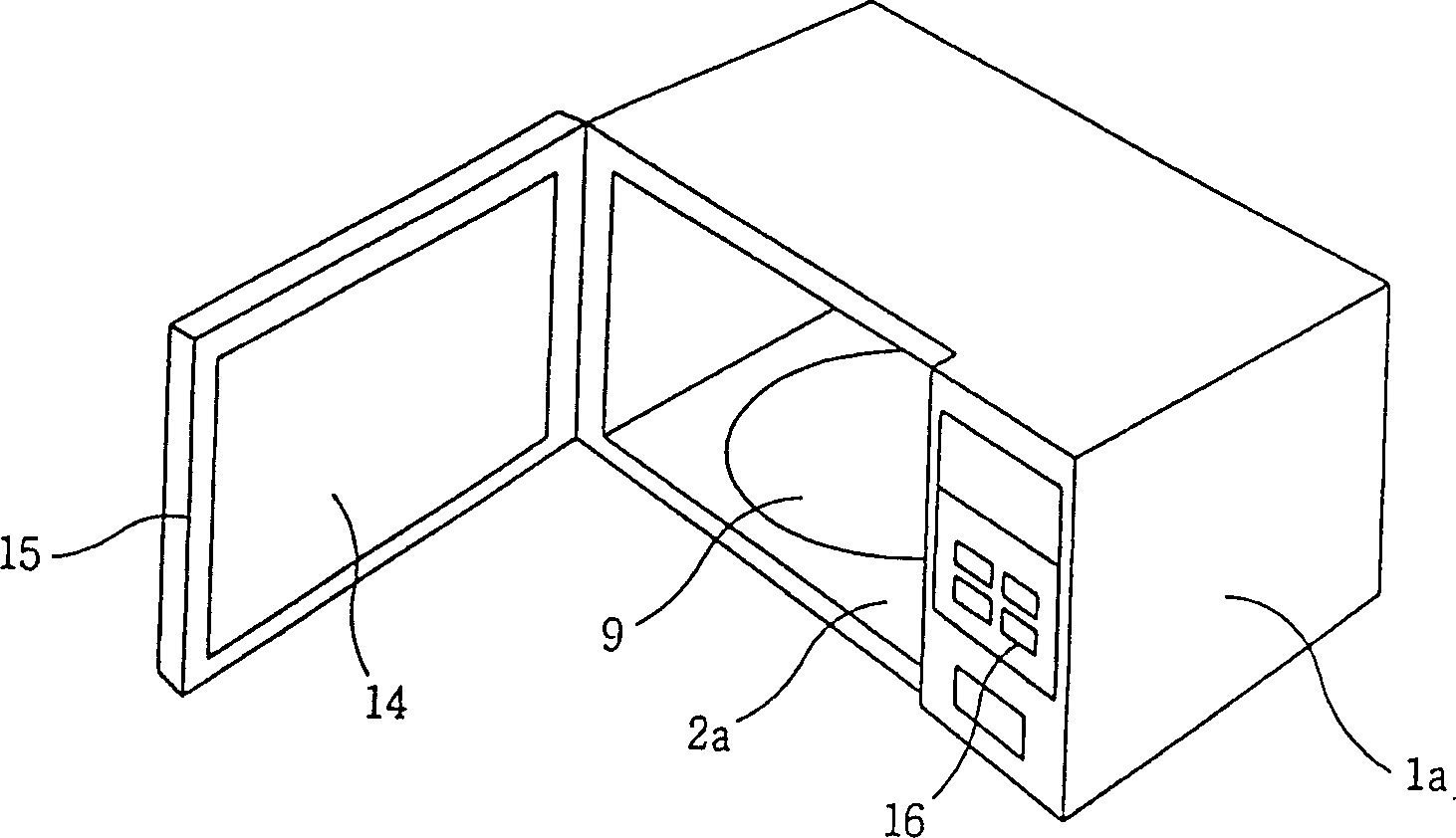
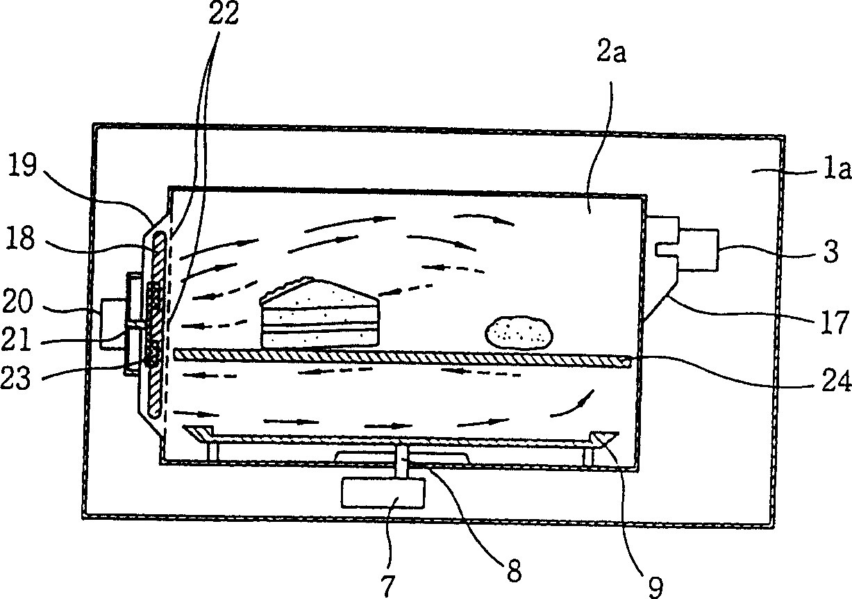
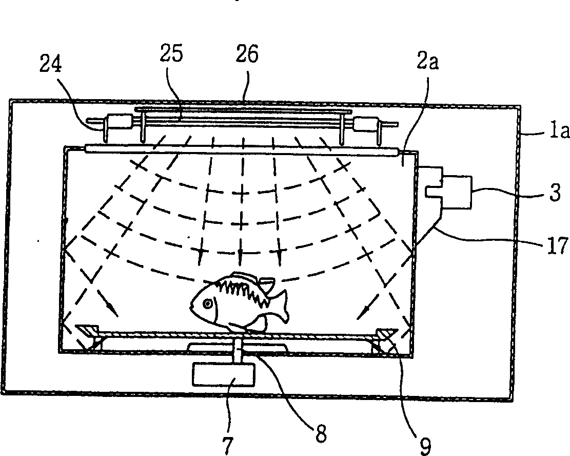
[0032] Such as Figure 4 with 7 As shown, the microwave oven of the present invention includes a cooking chamber 2 with a specific area for cooking food, a magnetron 3 installed outside the cooking chamber 2, a waveguide 4 with two-way flow channels 4a, 4b installed inside the waveguide 4 The microwave guide plate 5, and the plasma lamp 13 installed adjacent to the side of the flow channel of the waveguide 4.

[0033] A waveguide 4 having a rectangular or tubular shape is mounted on the side of the magnetron 3 to guide microwaves inside the cooking chamber 2, and has two-way flow passages 4a and 4b whose ends face the inner bottom surface of the cooking chamber 2 The other end of the circulation passage faces the plasma lamp installed on the inner top surface of the cooking chamber 2.

[0034] A baffle-shaped microwave guide plate 5 is hinged to the b...


PUM


Abstract

The present invention relates to a microwave oven including a cavity having a certain area for cooking, a magnetron installed at the outside of the cavity for generating microwave, a waveguide installed at the side of the magnetron and its end extended inside of the cavity for transmitting the microwave inside of the cavity. The microwave oven comprises a bidirectional flow channel formed inside of the waveguide for transmitting microwave selectively inside of the cavity in accordance with cooking function, a microwave plate combined to inside of the waveguide so as to be rotational for guiding the microwave to selected direction between the two direction of the flow channel, and a plasma lamp installed adjacent to the side of the bidirectional flow channel for generating radiant energy by being heated by the microwave.

Description

technical field [0001] The present invention relates to microwave ovens, and more particularly to microwave ovens capable of convection cooking and grill cooking by including means for generating radiant heat and convecting the radiant heat inside a cooking chamber. Background technique [0002] Microwave ovens use the molecular motion of food produced by microwaves to cook food. [0003] A conventional microwave oven will now be described. [0004] Such as figure 1 As shown, a door 15 with a transparent door shield 14 is installed on the front of the main frame as a hinged door, and a control panel 16 for setting functions and cooking time is installed on the side of the door 15. [0005] A conventional microwave oven with a convection cooking function will now be described. [0006] Such as figure 2 As shown, there is a cooking chamber 2a in a specific area for cooking in the main frame 1a, the magnetron 3 is installed outside the cooking chamber 2a, and the waveguide...

Claims


Application Information

Patent Timeline
IPC IPC(8): F24C7/02H05B6/70H05B6/74H05B6/80
CPCH05B6/745H05B6/70H05B6/647F24C7/02
Inventor 柳钟馆金亮卿
Owner LG ELECTRONICS INC
Why Eureka
Try Eureka