Supercharge Your Innovation With Domain-Expert AI Agents!

Video signal transmission device

A technology for image signals and data recognition, which is applied in image communication, pulse modulation TV signal transmission, TV, etc., and can solve problems such as the need for manpower

Inactive Publication Date: 2004-06-23
SONY CORP
View PDF0 Cites 0 Cited by
  • Summary
  • Abstract
  • Description
  • Claims
  • Application Information

AI Technical Summary

Problems solved by technology

[0005] However, when broadcasting channels of a TV station are multi-channeled using, for example, a video server, monitoring each of these channels has the disadvantage of requiring a lot of manpower.

Method used


Image

  • Video signal transmission device
  • Video signal transmission device
  • Video signal transmission device

Examples


Embodiment Construction

[0019] Next, an embodiment of the video signal transmitting apparatus of the present invention will be described with reference to the drawings.

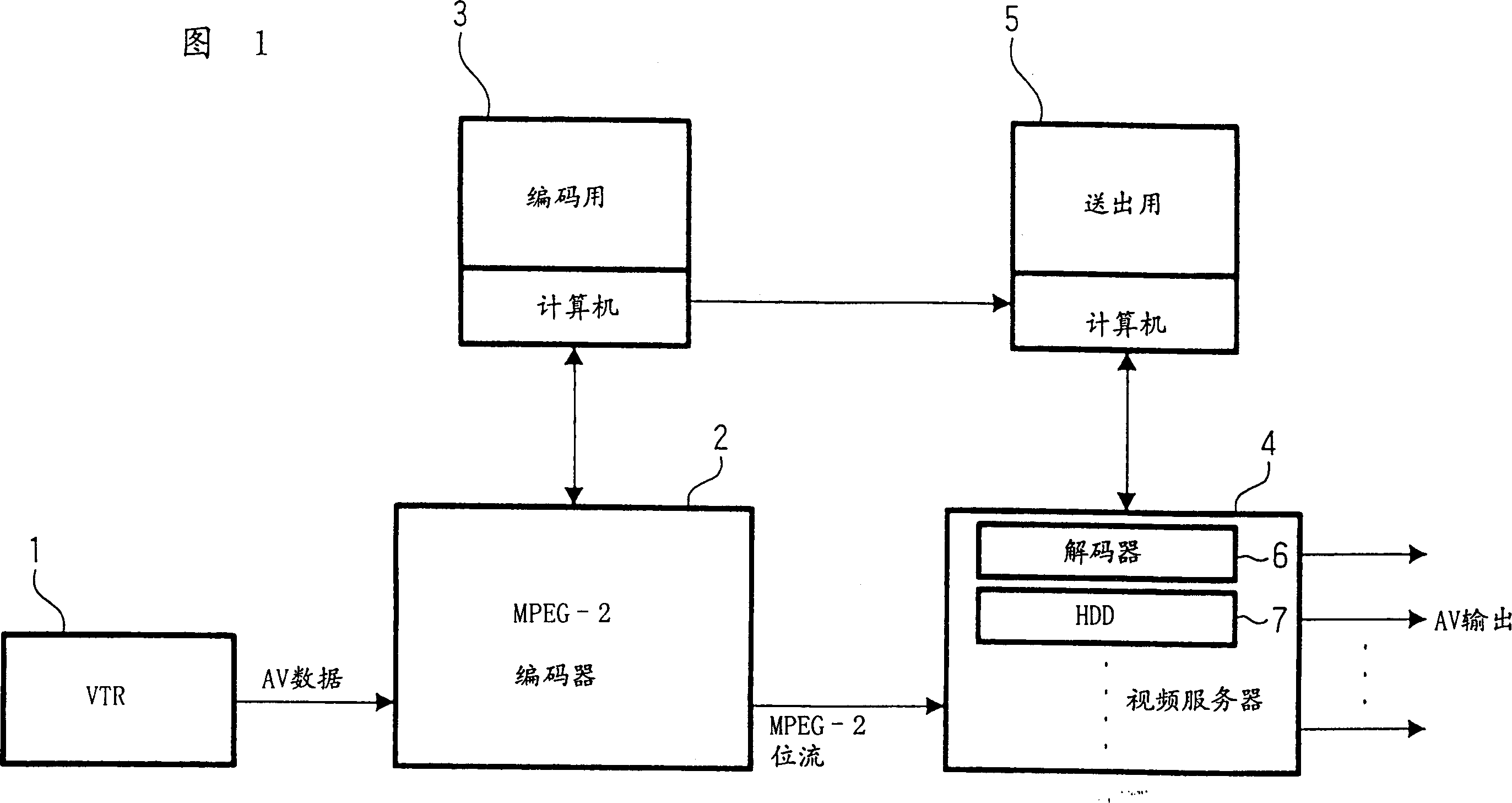
[0020] FIG. 1 shows the composition of the video signal sending device of this embodiment. In FIG. 1, 1 denotes a video tape recorder (VTR) for supplying image signals to be broadcast, and an MPEG-2 encoder 2 is supplied with image signals from the VTR 1, for example.

[0021] The MPEG-2 encoder 2 encodes the input video signal into MPEG-2 bit stream data in accordance with an instruction from the encoding computer 3 . As we all know, the MPEG-2 (Moving Picture Image Coding Experts Group Phase 2: Moving Picture Coding Experts Group Phase 2) is a standardized video and audio compression method formulated by ISO (International Organization for Standardization) and IEC (International Electrical Commission). Based on DCT (Discrete Cosine Transform), not only intra-frame correlation is used, but also inter-frame correlation is used usin...


PUM


Abstract

A video signal transmission apparatus has the encoding means 2, operative when a predetermined unit of video signal is compressively encoded, for multiplexing identification data unique to this video signal in a user data region within an encoded bit stream, and the storing / decoding means 4 for storing the encoded bit stream data having the unique identification data multiplexed therein, and, when transmission is requested from the outside, for decoding the encoded bit stream data and simultaneously reading the multiplexed unique identification data to verify whether it is unique identification data of a video signal to be transmitted.

Description

technical field [0001] The present invention relates to an image signal sending device for encoding an input image signal into coded data in a format represented by MPEG-2 (Moving Picture Image Experts Group Phase 2), storing and sending it. Background technique [0002] When a television station sends out video signals, it is generally checked whether the video signal to be sent has been sent without error, and such a check has been conventionally performed in the following manner. [0003] First, before sending out the multiple video signals, these multiple video signals are temporarily recorded on a video tape or the like in the order of sending them out. In this case, identification data unique to each image signal is inserted into the VITC (Vertical Interval Time Code: TV vertical scanning period) or LTC (Longitudinal Time Code: time code recorded on the vertical audio channel of the video tape) area. [0004] When sending these multiple image signals, the image signal...

Claims


Application Information

Patent Timeline
Patent Type & Authority Patents(China)
IPC IPC(8): H04N5/91H04N21/231H04N21/235H04N21/236H04N21/2383H04N21/2387H04N21/24H04N21/434H04N21/6405
CPCH04N21/2402H04N21/23614H04N21/6405H04N21/2383H04N21/2387H04N21/4348H04N7/16H04N21/2404G06F15/00
Inventor 松本昭彦月田竜雄石川裕一
Owner SONY CORP
Features
  • R&D
  • Intellectual Property
  • Life Sciences
  • Materials
  • Tech Scout
  • Unparalleled Data Quality
  • Higher Quality Content
  • 60% Fewer Hallucinations
Learn More