Sound reflector in hand set for controlling distance communicating tech.

A hand-held device and technology, applied in the direction of frequency/direction characteristic device, telephone communication, telephone structure, etc., to achieve good noise reduction effect

Inactive Publication Date: 2004-06-30
SIEMENS AG
View PDF0 Cites 0 Cited by
  • Summary
  • Abstract
  • Description
  • Claims
  • Application Information

AI Technical Summary

Problems solved by technology

[0012] However, the hole in the back of the earpiece capsule is detrimental to the aforementioned problem of poor sound attenuation because it causes sound to be reflected from the back of the diaphragm into the interior of the housing of the handheld

Method used


Image

  • Sound reflector in hand set for controlling distance communicating tech.
  • Sound reflector in hand set for controlling distance communicating tech.
  • Sound reflector in hand set for controlling distance communicating tech.

Examples


Embodiment Construction

[0032] It should be borne in mind here that when we speak of a handheld device, it can obviously also be a mobile or cordless phone.

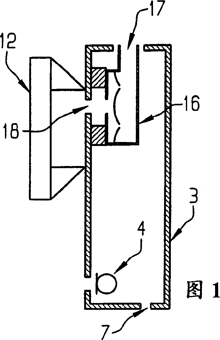
[0033] FIG. 1 shows the handheld device 3 of the present invention, wherein the back space of the earpiece carbon capsule 16 is connected with the outer space of the handheld device 3 through a sealing groove 17 . In addition, it is advantageous if the outlet of the slot 17 is located on the upper surface of the hand-held device.

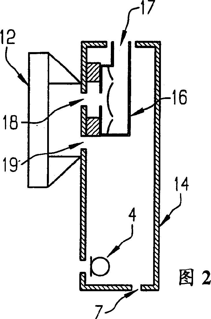
[0034] Fig. 2 shows an embodiment according to the present invention, in which a subwoofer structure is used. That is to say, the front of the earpiece capsule must communicate with the back without soundproofing, and the earphone and the front of the earpiece capsule are not allowed to form a complete seal. The handheld device 14 in FIG. 2 also has an earpiece carbon cartridge 16 with a groove 17 , wherein the earpiece carbon cartridge is spaced apart from the inner side of the housing having a sound discharge hole...


PUM


Abstract

The acoustic reflection suppression device has a channel (17) which is sealed with respect to the interior of the telephone handset, used for connecting the volume on the rear side of the hearing capsule (16) with the outside of the telephone handpiece at a point which is spaced from the ear of the user.

Description

technical field [0001] The present invention relates to a structure for suppressing sound reflections in a hand-held device for telephony technology. Background technique [0002] It is important that the telephone set be affected as little as possible by reflections of the received signal in order to allow unimpeded communication between the callers. Reflections occur not only in the telephone line area, but also in the handset area. In particular, the sound signal of the earpiece capsule is influenced by the microphone, and this sound signal is passed on to the telephone line. The caller thus has the impression of sound reflections, Hall effect and reverberation. [0003] Reasons for this are, for example, poor sound cancellation between the earphone and the handset microphone due to sound reflections inside the earpiece (acoustic feedback). [0004] Another disadvantage is that, especially at present, cordless and mobile phones are so extremely downsized that problems ...

Claims


Application Information

Patent Timeline
IPC IPC(8): H04M1/03H04M1/20H04R1/38
CPCH04M1/035H04R1/2888
Inventor H·佩特森
Owner SIEMENS AG
Why Eureka
Try Eureka