Monitor system with internal power supply

A monitoring system and monitored technology, applied in the field of monitoring systems, can solve the problems of reduced electromotive force, insufficient electromotive force for photocells, and complexity

Inactive Publication Date: 2004-07-14
TLV CO LTD
View PDF0 Cites 0 Cited by
  • Summary
  • Abstract
  • Description
  • Claims
  • Application Information

AI Technical Summary

Problems solved by technology

[0005] There are often such problems in the monitoring system of commercialized energy that uses existing driving energy. First, the transmission wire is too long and complicated, which increases the system cost; second, the photovoltaic cell cannot obtain enough electromotive force at night or indoors, or the If the surface of the light receiving plate becomes dirty, the electromotive force will also decrease; in addition, the thermal energy generating device cannot obtain a stable electromotive force

Method used


Image

  • Monitor system with internal power supply
  • Monitor system with internal power supply
  • Monitor system with internal power supply

Examples


Embodiment Construction

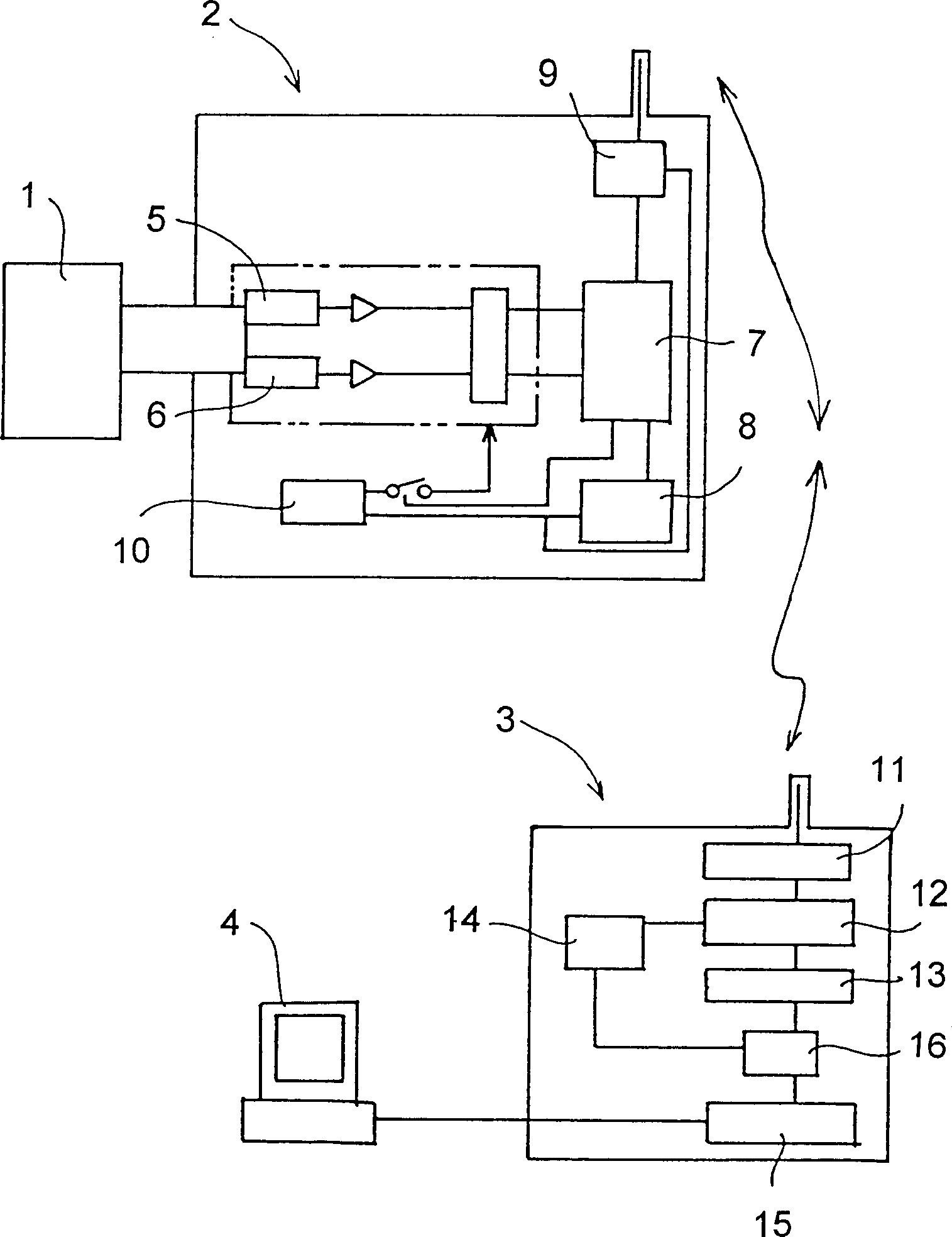
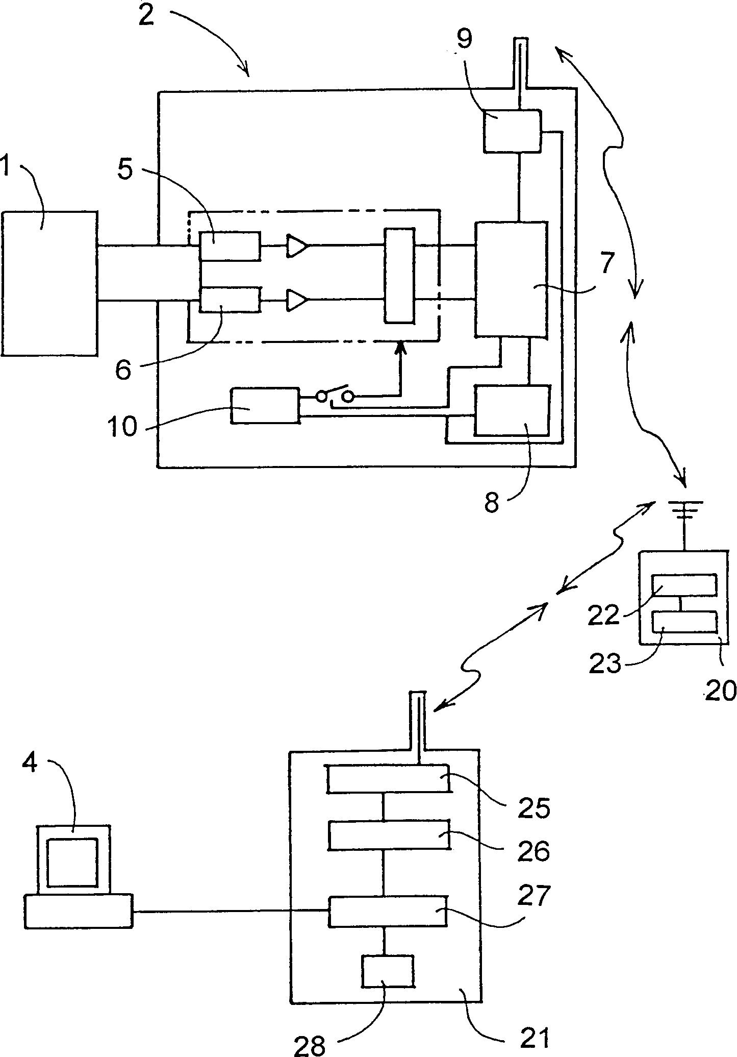
[0014] figure 1 The monitoring system shown, wherein the sensor unit 2 is directly connected to the monitored valve, separator (trap) 1, or similar parts, monitoring information is collected by a remote portable data recorder 3, detailed analysis of data, calculation operations and Display and storage etc. are performed by the computer 4 .

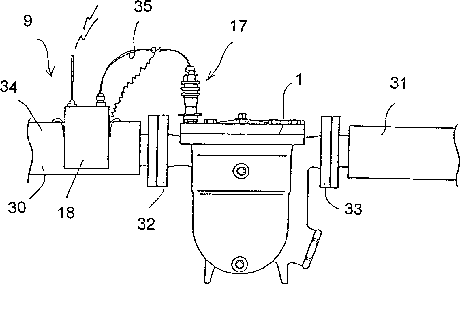
[0015] The installation method of the sensor unit 2 and the valve may be a fast connection, such as a screw connection, or a detachable connection through a joint. When the sensor unit 2 cannot be directly connected to the object to be monitored, the sensor unit 2 can be placed near the object to be monitored through a conversion component having a physical quantity corresponding to the object to be monitored. Of course, the sensor unit 2 can also be placed in the object to be monitored, such as a valve, separator 1 and so on.

[0016] Such as figure 1 The shown sensor unit 2 includes sensors 5 and 6 that can detect physical quantities,...


PUM


Abstract

The present invention aims to provide a monitoring system with a power supply built therein, which is capable of setting installation expenses at low cost and obtaining a stable result of monitoring for a predetermined period. The monitoring system comprises a sensor unit having sensors and a power supply incorporated therein, and a portable data logger having a communication module and a power supply built therein. Physical quantities such as vibrations, temperatures, and pressure, of an object to be monitored are detected by the sensors, followed by transmission to the portable data logger, whereby the state of operation of the object is displayed.

Description

technical field [0001] The present invention relates to a monitoring system for operating and inspecting valves installed on various piping systems in factories, such as pressure reducing valves, safety valves, automatic control valves, directional control check valves, and such as steam-water separators , air separators and other separators, and / or various equipment installed in the factory. More particularly, the present invention relates to a monitoring system with an internal power supply that is inexpensive to install and to obtain a stable monitoring output. Background technique [0002] The equipment in the factory, such as various rotating machinery, driving machinery, and valves controlling the flow of various fluids, are installed in large numbers on the production site of the factory. According to their importance, these equipment and valves need to check and monitor their operating conditions frequently or periodically in order to obtain maximum output with mini...

Claims


Application Information

Patent Timeline
Patent Type & Authority Patents(China)
IPC IPC(8): G01D21/00F17D3/00G01M99/00G05B19/042
CPCG05B19/0423G01D9/005F17D3/00
Inventor 永濑守
Owner TLV CO LTD
Why Eureka
Try Eureka