Magnetic resonance chromatographic instrument

A technology of magnetic resonance and tomography, applied in magnetic resonance measurement, material analysis through resonance, instruments, etc., can solve problems such as slow temperature adjustment, balance, and incomplete short-term fluctuation of heat source, and achieve small correction and low structural cost Effect

Inactive Publication Date: 2004-08-04
SIEMENS AG
View PDF2 Cites 0 Cited by
  • Summary
  • Abstract
  • Description
  • Claims
  • Application Information

AI Technical Summary

Problems solved by technology

Due to the thermal coupling to the yoke, only a relatively slow temperature regulation is possible here, and short-term fluctuations in the heat source are only partially balanced

Method used


Image

  • Magnetic resonance chromatographic instrument
  • Magnetic resonance chromatographic instrument
  • Magnetic resonance chromatographic instrument

Examples


Embodiment Construction

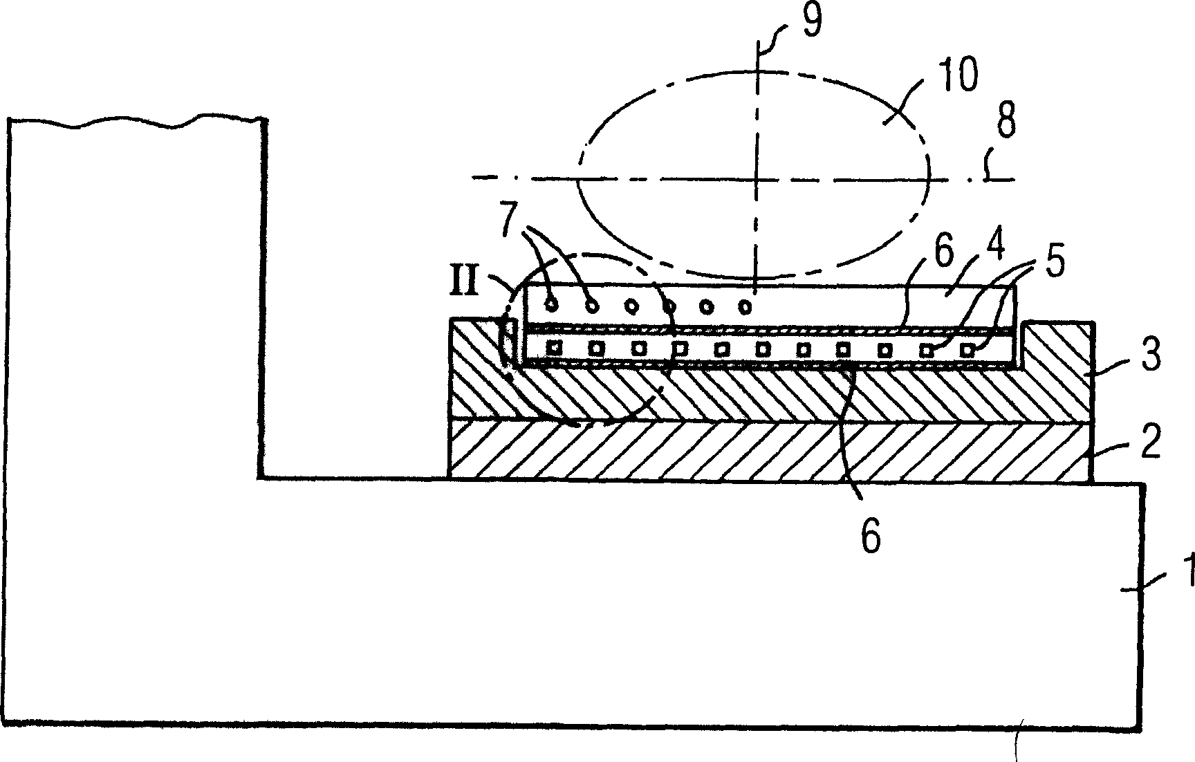
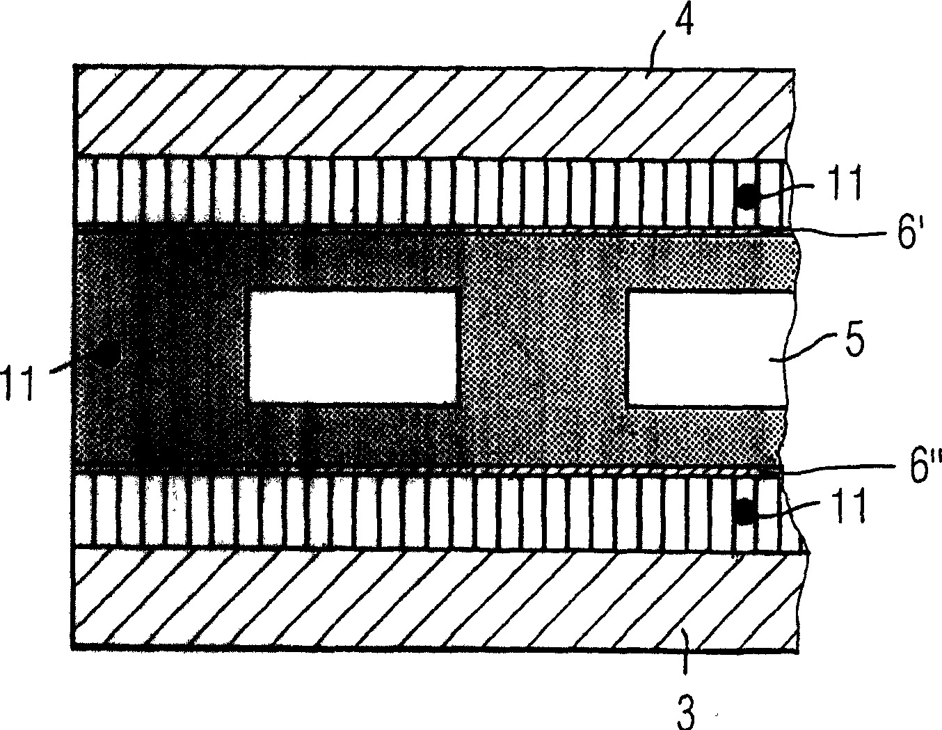
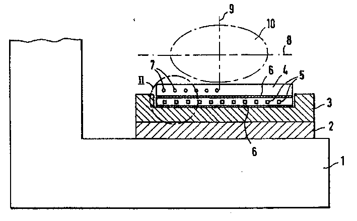
[0021] by figure 1 A permanent magnet 2 for generating the basic magnetic field is provided on the open C-shaped dome 1 of the partially shown magnetic resonance tomograph, on which the gradient coils are mounted, and the secondary gradient coils are designated by the reference numeral 3, The primary gradient coil is designated with reference numeral 4 . Between the two there are lining irons 5 which, in addition to other thermally highly sensitive components, also have a particularly strong influence on the homogeneity of the basic magnetic field of the system. In order to keep the necessary constant temperature here, between the backing iron 5 and the gradient coils 3 and 4, the heating films 6' and 6" of a thin film heater 6 are arranged respectively, preferably double-strand coils, so as to pass through the The heating of this heating film retreats to balance the disturbing heat source.Reference numeral 7 represents a common water cooling device, which is arranged in the ...


PUM


Abstract

A magnetic resonance tomography apparatus, in particular an iron-guided or permanently magnetic, short or open magnetic resonance tomography apparatus, has thermally highly sensitive components and a temperature controller, formed by a foil heater which is provided with a control device and can be controlled in opposition to the internal dynamic heat sources.

Description

technical field [0001] The invention relates to a magnetic resonance tomograph, in particular a short or open magnetic resonance tomograph (MTR) with iron guidance or permanent magnet excitation, which has thermally sensitive parts and a temperature regulator. Background technique [0002] In iron-guided or permanent magnet-excited magnetic resonance tomographs there are thermally highly sensitive components which strongly influence the homogeneity of the basic magnetic field. These are, for example, permanent magnets, lining iron (Schimeisen) or the like. These components must be stabilized in temperature, since compensation by software for the effects of these often large-area components is only possible under certain conditions. [0003] Dynamic thermal influences arise, for example, from fluctuations in room temperature or cooling water temperature, as well as time-dependent resistive losses in gradient coils or eddy current losses in the components themselves. In the ...

Claims


Application Information

Patent Timeline
Patent Type & Authority Patents(China)
IPC IPC(8): G01R33/389A61B5/055G01R33/31H01F5/00
CPCG01R33/31
Inventor 鲁道夫·罗克莱因克劳斯·施莱克尔
Owner SIEMENS AG
Why Eureka
Try Eureka