
Electronic camera having pixel-row thinning mode

a technology of pixel-row thinning and electronic cameras, which is applied in the direction of still video cameras, color signal processing circuits, television systems, etc., can solve the problems of image sensor defect, image quality degradation, image sensor defect, etc., to minimize image defect, minimize image defect, and lighten the burden

Inactive Publication Date: 2007-02-08
FUJIFILM CORP
View PDF2 Cites 7 Cited by
  • Summary
  • Abstract
  • Description
  • Claims
  • Application Information

AI Technical Summary

Benefits of technology

[0008] In view of the foregoing, it is a primary object of the present invention to provide an electronic camera capable of reducing correction of line-shaped defects, which are likely to deteriorate image quality in comparison with dot defects and are caused by a vertical transfer path.
[0018] According to the present invention, when the pixel rows are thinned, the pixel rows to be read are controlled every imaging sensitivity so as to minimize the line-shaped defect extending in the vertical direction. Further, defect correction is performed only for the defective pixel rows included in the pixel rows to be read. Thus, it is possible to minimize the defect of the image obtained by thinning the pixel rows. In addition, since the defect correction is reduced, a burden thereof is lightened.

Problems solved by technology

In recent years, however, the image sensor is improved so as to have high pixel density and it is difficult in some cases to transfer the charge of all the pixels and to output the signal during a one-frame period.
Meanwhile, it is known that a defect occurs on the image sensor due to partial crystal faulty of a semiconductor and so forth.
The defect of the image sensor deteriorates image quality.
Besides this, there is line-shaped density unevenness caused by a low transfer rate of a part of the vertical transfer path.
However, it is difficult to produce the image sensor having no pixel and no vertical transfer path by which the defect is caused.
Further, after producing the image sensor, the defect is likely to occur when ultraenergetic particles of cosmic rays and so forth enter the image sensor.
By the way, although the occurrence of the dot defect to be caused by the defective pixel may be avoided to some extent, it has been impossible to avoid the occurrence of the line defect because the line defect is caused by the vertical transfer path.
However, when the many line defects occur, a processing period required for correcting the defects is long and a memory is excessively used for the purpose of correcting the defects.
Thus, there is a problem in that a frame rate, a shooting number and so forth are often restricted.
In addition, there is another problem in that image quality is likely to be deteriorated, although the line defects are corrected.

Method used


Image

  • Electronic camera having pixel-row thinning mode
  • Electronic camera having pixel-row thinning mode
  • Electronic camera having pixel-row thinning mode

Examples


Embodiment Construction

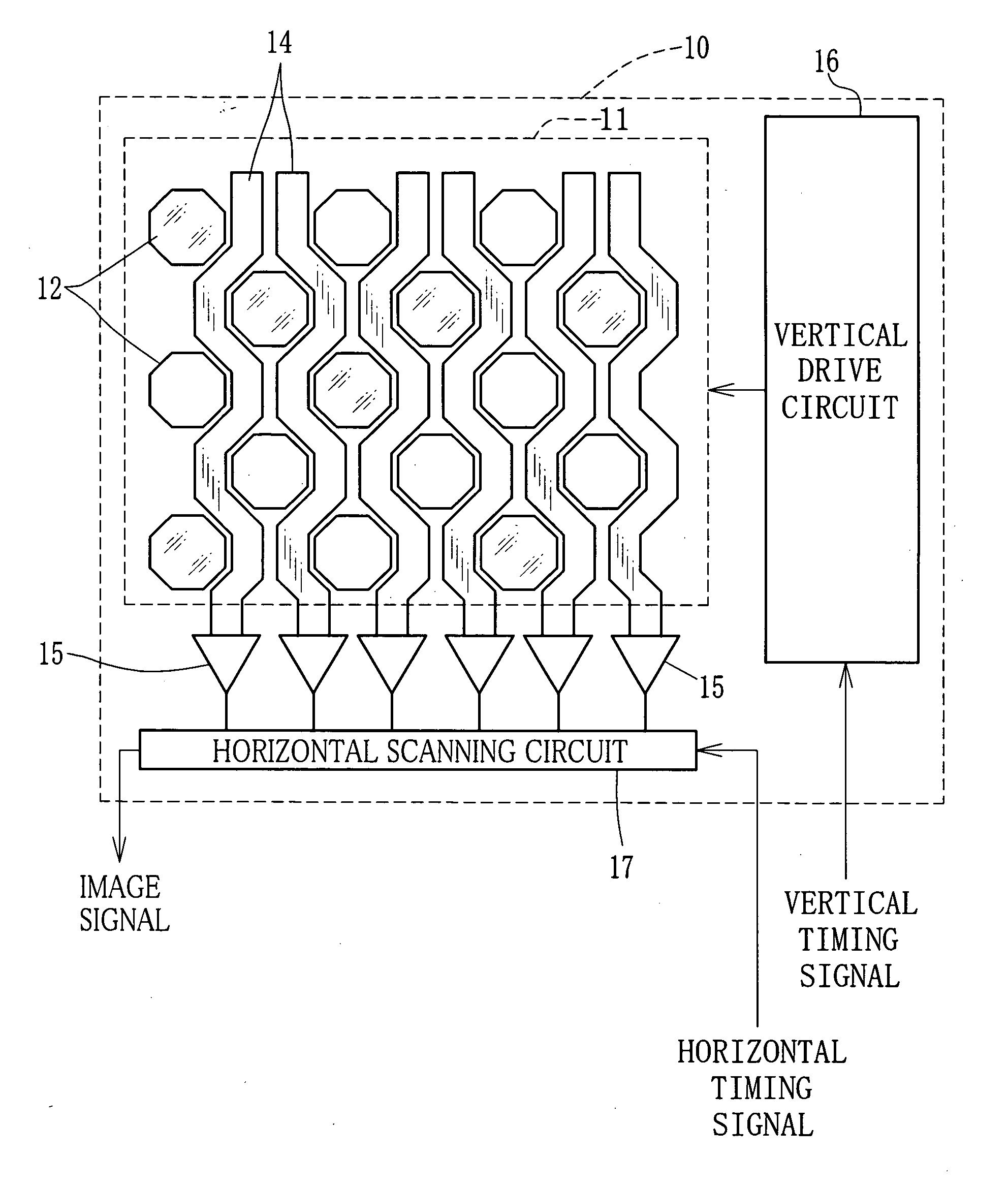
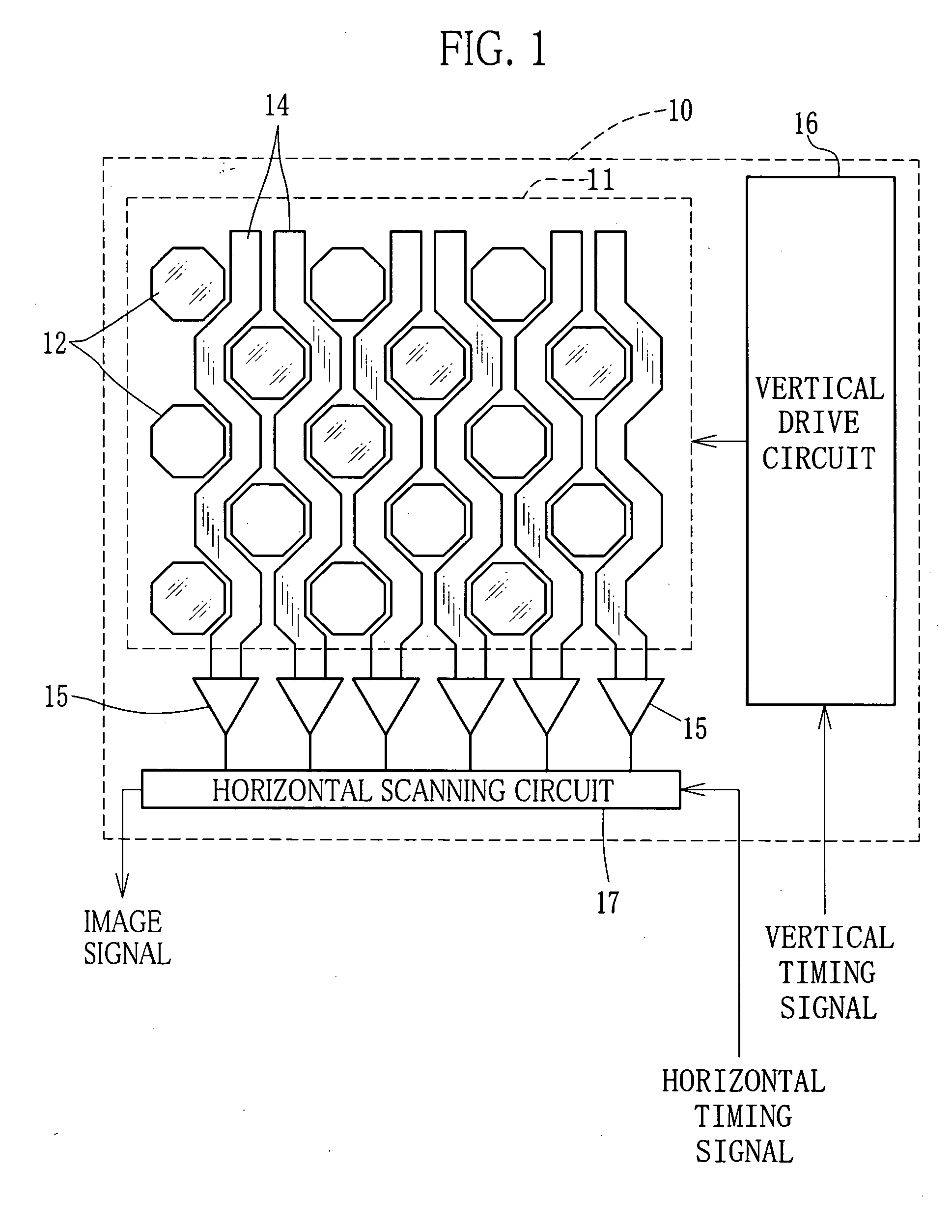
[0030]FIG. 1 schematically shows a structure of a CCD image sensor 10 used in an electronic camera according to the present invention. A light receiving surface 11 of the image sensor 10 is provided with a large number of pixels 12. The pixel 12 comprises a photodiode for photoelectrically converting incident light (subject light) and stores a signal charge in accordance with an amount of the incident light. The pixels 12 arranged in a horizontal direction compose a line, and the pixels 12 arranged in a vertical direction compose a row (hereinafter referred to as pixel row).

[0031] In the image sensor 10, the pixels 12 are arranged at constant pitch in the horizontal direction. In this regard, the pixels 12 of the respective lines are horizontally shifted by half the pitch relative to the pixels 12 of the adjacent lines. In other words, the pixels 12 have a honeycomb arrangement. In fact, about six million pixels 12 (about two thousand lines×three thousand rows) are arranged on the ...


PUM


Abstract

Pixel rows of an image sensor are respectively provided with a vertical transfer path. A charge detecting amplifier is disposed at one end of each of the vertical transfer paths. When a through image is outputted and when a moving-image mode is executed, a horizontal scanning circuit sequentially selects the charge detecting amplifiers on the basis of a thinning pattern, which is determined every imaging sensitivity, to output an image signal in which the pixel rows are thinned. As the thinning pattern, there are an odd-row pattern for selecting only the odd pixel rows from among the whole pixel rows, and an even-row pattern for selecting only the even pixel rows therefrom. The thinning pattern is selected in accordance with the imaging sensitivity so as to minimize line-shaped defects caused by the vertical transfer paths.

Description

FIELD OF THE INVENTION [0001] The present invention relates to an electronic camera having a pixel-row thinning mode. BACKGROUND OF THE INVENTION [0002] In recent years, electronic cameras are widely used. This kind of the electronic camera is provided with an image sensor for converting an optical subject image into an electrical signal. With respect to the image sensor, a CCD type and a CMOS type are mainly used. As a trend, the CCD image sensor is widely utilized because of advantage concerning high pixel density. [0003] As to the CCD image sensor, there are an interline-type CCD, a frame-transfer-type CCD and so forth. For instance, the interline-type CCD is composed of a large number of pixels, a vertical transfer pass (vertical CCD), a horizontal transfer path (horizontal CCD), a charge detecting amplifier and so forth. The pixels comprise photo diodes and are arranged in a matrix. The vertical transfer path is provided for each pixel row including the pixels arranged in a ver...

Claims


Application Information

Patent Timeline
IPC IPC(8): H04N5/335H04N5/341H04N5/345H04N5/357H04N5/363H04N5/372H04N5/378H04N101/00
CPCH04N5/343H04N5/372H04N5/367H04N5/3452H04N25/441H04N25/42H04N25/68H04N25/71
Inventor KOBAYASHI, HIROKAZUODA, KAZUYA
Owner FUJIFILM CORP
Learn More