Electric actuator having rotation stopping function

An actuator and function technology, applied in the direction of electric components, circuits, couplings, etc., can solve problems such as increasing the manufacturing cost of electric actuators, and achieve the effect of preventing rotation

Inactive Publication Date: 2004-09-08
SMC CORP
View PDF0 Cites 0 Cited by
  • Summary
  • Abstract
  • Description
  • Claims
  • Application Information

AI Technical Summary

Problems solved by technology

This has just had the problem of greatly increasing the manufacturing cost of electric actuator 40,50,60

Method used


Image

  • Electric actuator having rotation stopping function
  • Electric actuator having rotation stopping function
  • Electric actuator having rotation stopping function

Examples


Embodiment Construction

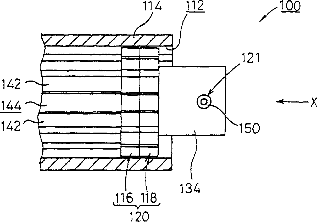
[0025] in figure 1 Above, reference numeral 100 denotes the rotation stop device of the first embodiment of the present invention.

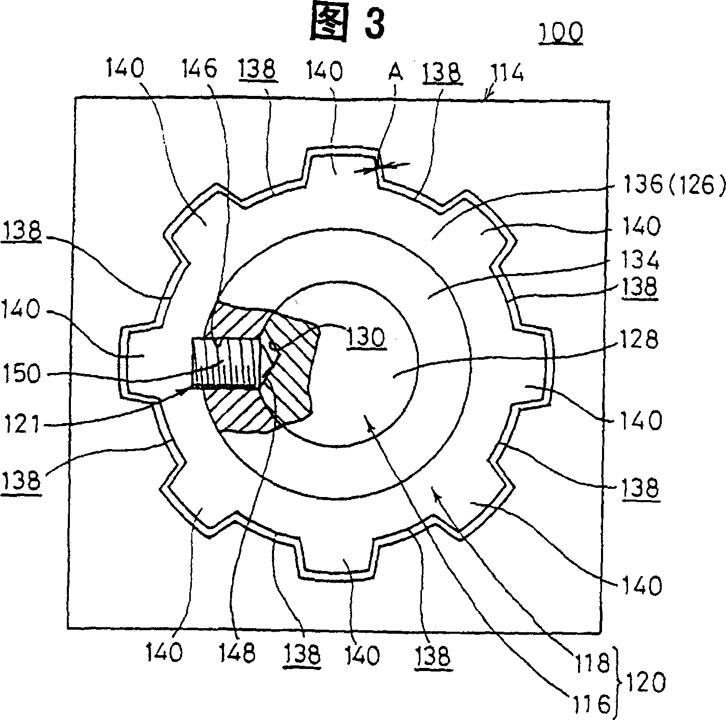
[0026] The anti-rotation device 100 is composed of a sleeve portion 114, a spline shaft 120, and a gap adjustment mechanism 121. Wherein, the sleeve portion 114 is approximately circular in cross-section, and a through hole 112 is formed along the axial direction; the spline shaft 120 is coaxially connected to the separated first spline shaft member 116 and the second spline shaft member 118, two splines The shaft members 116, 118 are arranged to be freely slidable along the hole 112; the gap adjustment mechanism 121 is used to adjust the circumferential gap A formed between the inner wall surface of the sleeve portion 114 and the outer wall surface of the spline shaft portion 120 (see Figure 3).

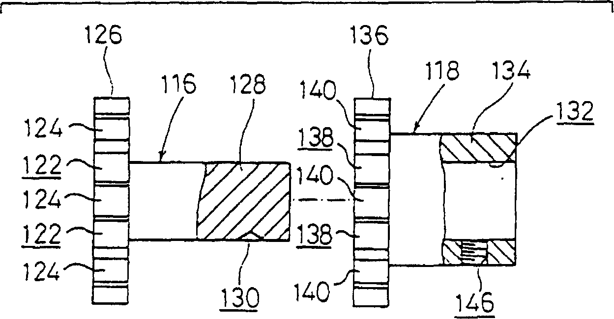
[0027] Such as figure 2 As shown, the first spline shaft member 116 has a circular plate portion 126 and a shaft portion 128. Among them, the circular p...


PUM


Abstract

A rotation stop device comprising a mechanism (121) for regulating a circumferential clearance (A) between an inner surface of a boss (114) and an outer surface of a spline shaft (120) by turning two-split first and second spline shaft members (116, 118) in the mutually opposite directions on the axes thereof.

Description

Technical field [0001] The present invention relates to, for example, a rotation stop device that can perform circumferential rotation stop of the spline shaft by combining a spline shaft with a sleeve hole, and an electric actuator having a rotation stop function. Background technique [0002] From the perspective of the prior art, for example, a spline is used as a circumferential rotation stop of a shaft member. Such as Figure 23 As shown, this spline 1 has a spline shaft 4 and a sleeve 6. Among them, the spline shaft 4 forms a plurality of teeth 3a to 3h with a slightly truncated cross section between adjacent grooves 2a to 2h spaced at a predetermined angle along the circumferential direction of the outer peripheral surface; the sleeve 6 is relatively free to slide along The spline shaft 4 is arranged in the axial direction, and a hole 5 corresponding to the cross-sectional shape of the spline shaft 4 in the direction perpendicular to the axis is formed. [0003] In this ca...

Claims


Application Information

Patent Timeline
IPC IPC(8): F16C29/02F16D3/06F16H25/20H02K7/06H02K7/102
CPCH02K7/06F16H25/20F16D3/06H02K7/102F16C29/02F16H2025/2034F16H2025/204Y10T74/18656Y10T403/7028F16H57/0025F16H2025/2445
Inventor 永井茂和白井庸介
Owner SMC CORP
Why Eureka
Try Eureka