Method for forming end face electrode

An end-face electrode and side-electrode technology, which is applied to the formation of electrical connection of printed components, circuits, electrical components, etc., can solve problems such as thermal deformation of fixing clamps, and achieve the effect of eliminating bending, preventing defects, and improving production.

Inactive Publication Date: 2004-09-29
MURATA MFG CO LTD
View PDF0 Cites 0 Cited by
  • Summary
  • Abstract
  • Description
  • Claims
  • Application Information

AI Technical Summary

Problems solved by technology

At this time, thermal deformati

Method used


Image

  • Method for forming end face electrode
  • Method for forming end face electrode
  • Method for forming end face electrode

Examples


Example Embodiment

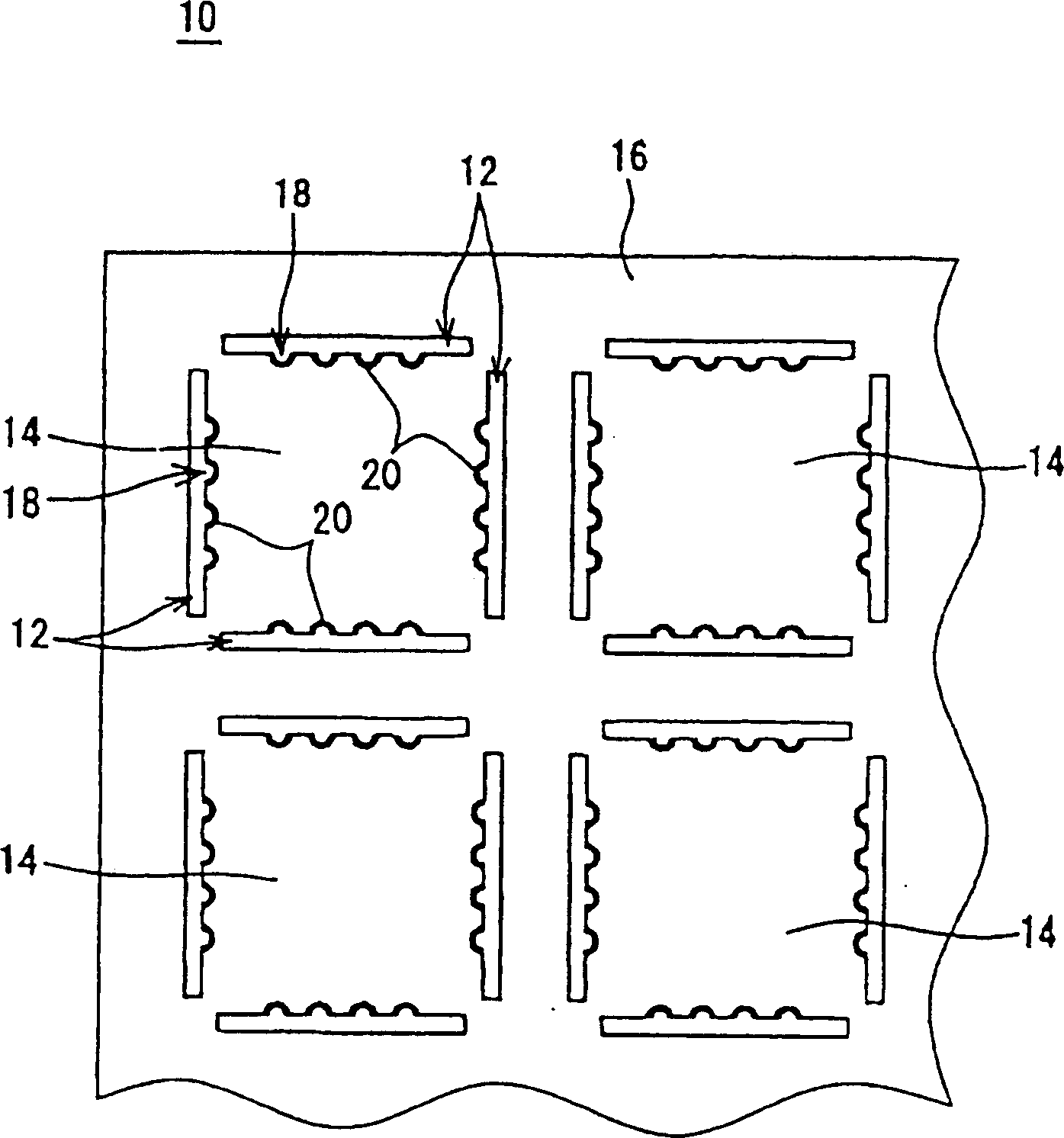
[0056] figure 1 is a plan view showing a master substrate used in the method of forming an end face electrode according to the present invention. There is provided a master substrate 10 having a plurality of linear slits 12 formed thereon. With these slits 12, a plurality of rectangular module substrates 14 are formed and waste substrates 16 are formed around them. In the sides of the slot 12 , at the end of the module substrate 14 , a plurality of hemispherical holes 18 are formed at a distance from each other. In the hole 18, the side electrode 20 is formed so that one main plane or two main planes of the hole 18 appear from its end face. On one plane of the module substrate 14, electrode wirings (not shown) are formed, and electronic components (not shown) are mounted on the electrode wirings to form a plurality of circuits. In order to connect the thus formed circuit to an external circuit, electrode wiring is connected to the side electrode 20 . By cutting these mult...


PUM


Abstract

There is provided a method for forming end-face electrodes in which the end-face electrode can be securely formed with solder at a position in which a side electrode is formed and it can be formed without being affected by a jig for fixing a solder solid. By forming linear gaps on a master substrate, module substrates and a waste substrate are formed. At the side end of the gap of the module substrate, a side electrode is formed. A solder solid is pressed into the part of the gap in which the side electrode is formed and a reflow jig is placed. The surface of the solder solid is coated with flux and the solder solid is melted by heating so as to form the end-face electrode protruding from the substrate surface in the side electrode.

Description

technical field [0001] The present invention relates to a method of forming end-face electrodes, and more particularly, to a method of forming end-face electrodes with solder on the end faces of substrates on which electronic components such as module assemblies are mounted. Background technique [0002] Figure 18 is a plan view of a host substrate used in the conventional formation method of facet electrodes. The master substrate 1 has a plurality of linear slits 2 formed thereon. With these slits 2, a plurality of rectangular module substrates 3 are formed on the main substrate 1, and waste substrates 4 are formed around them. On the end face of the module substrate 3, a plurality of side electrodes 5 are formed in spaces between adjacent electrodes 5 against the waste substrate 4 interposed in the gap therebetween. On the module substrate 3, electrode wirings (not shown) are formed. Then, electronic components (not shown) are mounted on the module substrate 3 so that ...

Claims


Application Information

Patent Timeline
IPC IPC(8): B23K1/00B23K1/20B23K37/04H01L21/48H01L23/498H05K3/00H05K3/34H05K3/40
CPCH05K3/403H01L2924/0002H05K2203/043B23K37/0443H05K3/3478B23K1/203H05K2203/041H01L21/4846H01L23/49805B23K1/0008H05K3/0052H01L2924/00
Inventor 毛利浩明芝田静司
Owner MURATA MFG CO LTD
Why Eureka
Try Eureka