Filter with adjustable bandwidth

A filter device and bandwidth technology, applied in the direction of impedance network, electrical components, multi-terminal pair network, etc., can solve the problem of low cost

Inactive Publication Date: 2004-10-20
WISTRON CORP +1
View PDF0 Cites 0 Cited by
  • Summary
  • Abstract
  • Description
  • Claims
  • Application Information

AI Technical Summary

Problems solved by technology

However, the cost of using two filters is still not low

Method used


Image

  • Filter with adjustable bandwidth
  • Filter with adjustable bandwidth
  • Filter with adjustable bandwidth

Examples


Embodiment Construction

[0028] In order to make the above-mentioned purposes, features, and advantages of the present invention more obvious and understandable, a preferred embodiment is enumerated below, and detailed description is as follows with reference to the accompanying drawings:

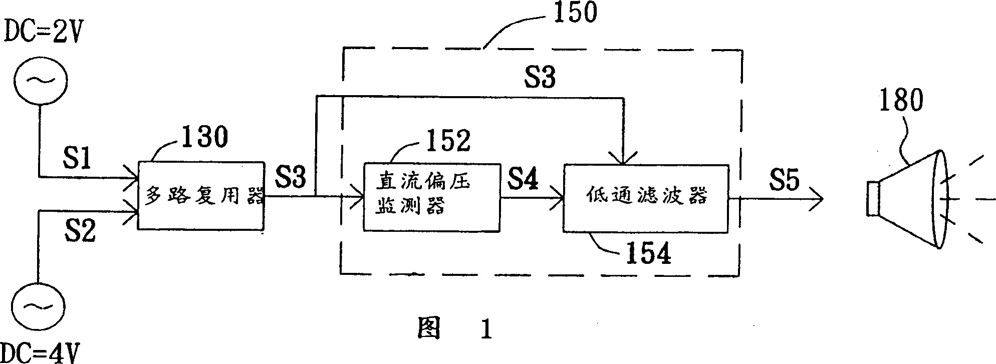
[0029] Referring to FIG. 1, it is a block diagram showing a preferred embodiment of the present invention. As shown in FIG. 1 , there are two sources of the first output signal S3 to be processed by the filtering device 150 , one is the voice signal S1 and the other is the MP3 signal S2 . The voice signal S1 and the MP3 signal S2 each include an AC signal and a DC bias voltage, and the DC bias voltages of the voice signal and the MP3 signal can be set to different DC bias voltages. For example, the DC bias of the voice signal S1 is 2V, and the DC bias of the MP3 signal S2 is 4V. Before the filtering device 150, a multiplexer 130 can be arranged, and this multiplexer 130 can receive signals from different sources, ...


PUM


Abstract

The filter set in the output unit of comprehensive system to receive the first output signal including AC signal and AC bias includes a DC bias monitor for receiving the first output signal and obtaining a control voltage based on the DC bias in the first output signal; and a low-pass filter connected electrically to the DC bias monitor for receiving control voltage and regulating the bandwidth of the low-pass filter. The low-pass filter is used to receive the first output signal and obtain the second outupt signal from the first output signal as the filter output for bandwidth regulation. The low-pass filter also includes a variable resistor with resistance varying with the control voltage magnitude.

Description

technical field [0001] The present invention relates to a filtering device, in particular to a filtering device which can automatically change the frequency width for signals of different properties. Background technique [0002] In recent years, due to the progress of science and technology, the function of the general integrated system in processing video and audio information has also been enhanced day by day. Taking sound signals as an example, most of the signals processed in the past are human speech signals, for example, the sound of conversations on the phone. However, with the development of the Internet, some electronic music files, such as MP3, are also popular. Therefore, the output unit in the integrated system has to deal with two signals with completely different bandwidth requirements. Some MP3 music files that require high fidelity have a bandwidth of up to 22KHz. However, the bandwidth of telephone voice is only 3KHz because of ...

Claims


Application Information

Patent Timeline
Patent Type & Authority Patents(China)
IPC IPC(8): H03H7/01H03H7/12
Inventor 李政宜
Owner WISTRON CORP
Why Eureka
Try Eureka