Laser multiple degree-of-freedom measuring system and method

A technology of measurement system and degree of freedom, applied in the field of laser precision measurement system, can solve problems such as difficult to achieve fast and convenient measurement, inconvenient on-site measurement, complex optical system, etc., to achieve convenient measurement, simple structure, and simple optical path adjustment Effect

Inactive Publication Date: 2004-11-24
BEIJING JIAOTONG UNIV
View PDF3 Cites 1 Cited by
  • Summary
  • Abstract
  • Description
  • Claims
  • Application Information

AI Technical Summary

Problems solved by technology

[0004] 1. Traditional geometric optics methods: such as (1) "Optical apparatus for indicating and measuring the roll angular orientation of a movable body" [Optical apparatus for indicating and measuring the roll angular orientation of a movable body, patent number: 3269254, 1966], (2) "Three-axis optical alignment device" [Three-axis optical alignment device, Patent No.: 3375750, 1968], (3) "Three-axis angle sensor" [Three-axis angle sensor, Patent No.: 4560272, 1985], etc. are the 20 In the 1960s and 1980s, there were researches and patents in this field. These patented technologies used traditional optical methods, using ordinary light sources as illumination, and had defects such as complex optical systems, low measurement accuracy, and few measurement parameters.
[0005] 2. Using the diffraction phenomenon of light: such as (1) "Multi-axis optical alignment system including a spatial filter" [Multi-axis optical alignment system including a spatial filter, patent number: 3701602, 1972], (2) "Three Three and five axis laser tracing system” [Three and five axis laser tracing system, Patent No.: 4714339, 1987], (3) “Multi-axis alignment apparatus” [Multi-axis alignment apparatus, Patent No.: 4804270, 1989], etc. The simultaneous measurement of three-dimensional angles is realized by using the diffraction phenomenon of light or the holographic grating. The disadvantages are that the measurement accuracy is not high, the measurement parameters are few, the optical system is complex, and the measurement head is equipped with a follower cable, which makes on-site measurement inconvenient.
[0006] 3. Methods based on laser tracking measurement: such as (1) "Laser tracking measurement system and measurement method for target spatial position and attitude" [China Patent Application No. 99109623.1], etc. This type of measurement method has a large measurement range and high measurement speed. However, there are defects such as low measurement accuracy, complex measurement system, and expensive measurement equipment.
In addition, almost all of these systems require cables to connect the moving measuring head to the rest of the measuring instrument, making quick and easy measurements difficult

Method used


Image

  • Laser multiple degree-of-freedom measuring system and method
  • Laser multiple degree-of-freedom measuring system and method
  • Laser multiple degree-of-freedom measuring system and method

Examples


Embodiment approach 1

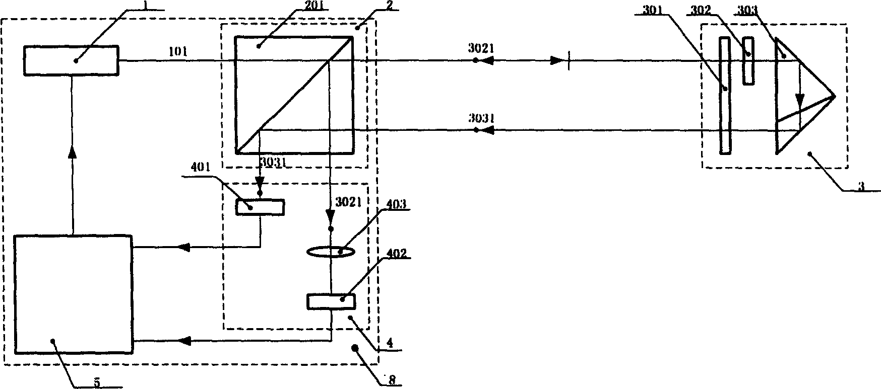
[0034] Implementation mode one ( figure 1 ):

[0035] The four-degree-of-freedom error sensitive unit 3 in the system is composed of a λ / 4 wave plate 301 , a beam splitter 302 and a light reflector 303 . The λ / 4 wave plate 301, the beam splitter 302 and the light reflector 303 are arranged along the direction of the incident light, and are fixed together by brackets or other means; the said λ / 4 wave plate 301 changes linearly polarized light into circularly polarized light, Or change circularly polarized light into linearly polarized light, said beam splitter 302 divides one beam of incident light into at least two beams of light, one beam is reflected, and the other beam is transmitted, and said light reflector 303 reflects the incident light back , but does not coincide with the original incident light. The beam splitter 302 is fixed on the incident light path of the light reflector 303, and the light 3031 reflected by the light reflector 303 of the incident light no longe...

Embodiment approach 2

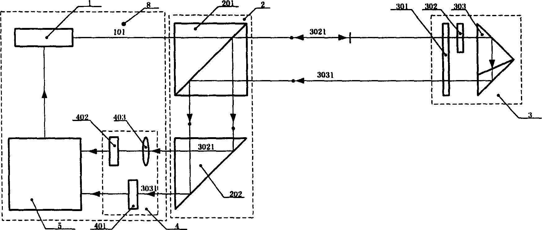
[0036] Implementation mode two ( figure 2 ):

[0037] The difference from Embodiment 1 lies in: the polarizing beam splitting unit 2 , which is composed of a polarizing beam splitter 201 and a total reflector 202 . The total reflector 202 and the polarizing beam splitter 201 can be connected separately or directly connected together. At the same time, the total reflector 202 can be a right-angle reflective prism or a plane mirror; the polarizing beam splitter unit 2 can be connected together with the fixed measuring head 8 of the measuring system, and can also be connected separately.

Embodiment approach 3

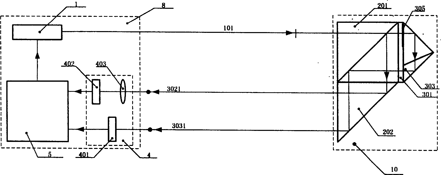
[0038] Implementation mode three ( image 3 ):

[0039] The difference from Embodiment 1 and Embodiment 2 is that in the four-degree-of-freedom error-sensitive unit 3, the light-splitting film 305 is directly coated on the incident side or the outgoing light side of the light reflector 303, and the light-splitter is removed. 302. At the same time, the polarization beam splitting unit 2 and the four-degree-of-freedom error sensitive unit 3 are directly connected together to form the movable measuring head 10 of the measuring system. On the fixed measuring head 8 of the measuring device, only the laser transmitter 1 , the photoelectric receiving unit 4 and the signal processing unit 5 are installed.


PUM


Abstract

A multi-freedom laser measuring system is composed of laser emitter, polarizing-splitting unit, 4-freedom error sensing unit, photoelectric receiver unit and signal processing unit. Said 4-freedom error sensing unit consists of quater-wavelength wave plate, optical splitter and optical reflector. The laser beam is splitted into the perpendicular mutually linear polarized light beams in two polarizing directions. The light beam received by said 4-freedom error sensing unit is splitted to two beans received by two photoelectric receiver. The linearity error of an object in two directions and the pitch angle error can be obtained after signal processing.

Description

(1) Technical field [0001] The invention relates to a laser precision measurement system and method, which is especially suitable for simultaneous measurement of multi-degree-of-freedom errors or motion postures of workpieces or objects when they move along a guide rail. (2) Background technology [0002] The detection of the accuracy of CNC machine tools and machining centers is an indispensable key link in the machine tool industry and machining industry, and is also an important means to ensure the machining accuracy and product quality of machine tools. To sum up, machine tool accuracy detection is mainly used in the following occasions: 1) Measure and draw the geometric accuracy error curve of the machine tool to correct and compensate the geometric error of the machine tool; 2) Conduct a decisive test on the new machine tool to be purchased to determine whether to purchase it ; 3) Periodic inspection of existing machine tools to ensure the machining accuracy of the mac...

Claims


Application Information

Patent Timeline
Patent Type & Authority Patents(China)
IPC IPC(8): G01B11/26G01B21/04G01J4/00
Inventor 冯其波
Owner BEIJING JIAOTONG UNIV
Why Eureka
Try Eureka