Multicolour light-emitting dispersed type electroluminescence lamp
A technology of light-emitting lamps and luminous bodies, which is applied in the direction of electroluminescent light sources, light sources, electric light sources, etc., and can solve problems such as color interference
- Summary
- Abstract
- Description
- Claims
- Application Information
AI Technical Summary
Problems solved by technology
Method used
Image
Examples
Embodiment 1
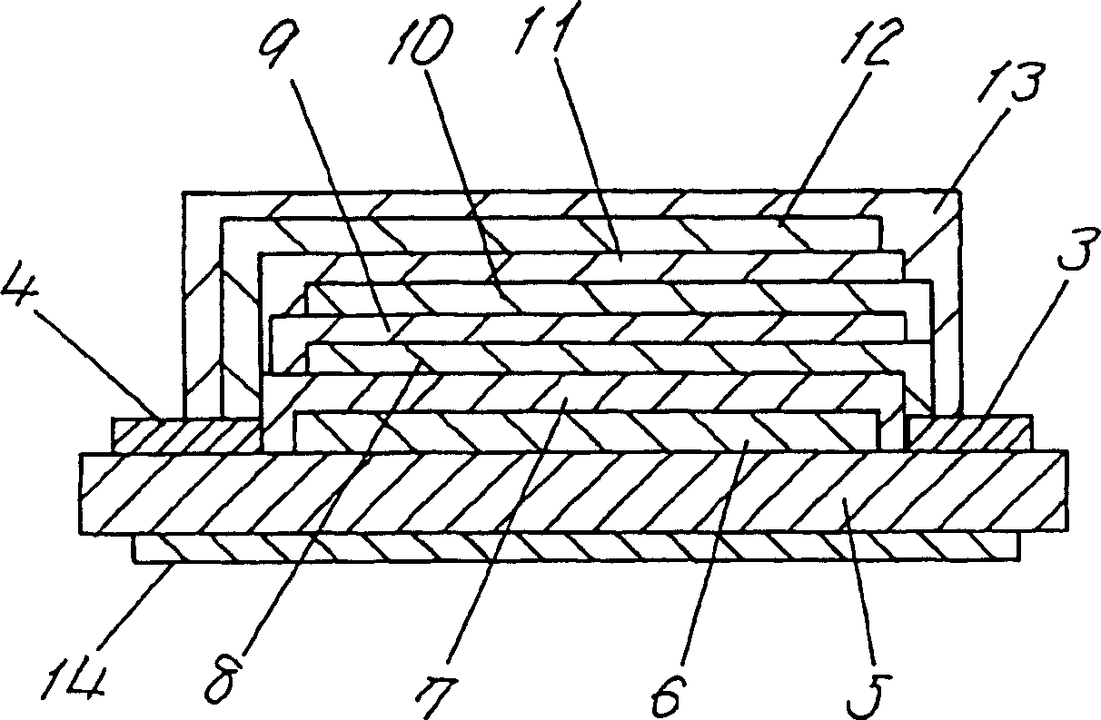
[0141] figure 1 A sectional view showing a polychromatic emission dispersion type EL lamp according to a first exemplary embodiment of the present invention. exist figure 1 Among them, the multi-color light-emitting dispersion type EL lamp has: a transparent resin film 5, a first translucent electrode layer 6 disposed on the first surface side of the transparent resin film 5, a first translucent electrode layer 6 disposed on the first translucent electrode layer 6 A luminous body layer 7, a second light-transmitting electrode layer 8 disposed on the first light-emitting body layer 7, a luminous color conversion layer 9 disposed on the second light-transmissive electrode layer 8, and a luminous color conversion layer 9 disposed on the The third light-transmitting electrode layer 10 on the third light-transmitting electrode layer 10, the second light-emitting body layer 11 on the third light-emitting body layer 10, the back electrode layer 12 on the second light-emitting body...
Embodiment 2
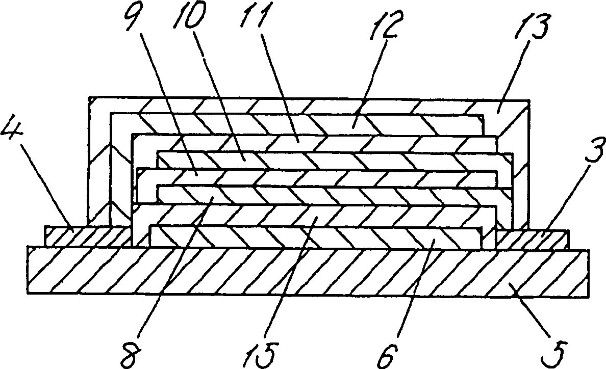
[0163] figure 2 A cross-sectional view showing a polychromatic emission dispersion type EL lamp according to a second exemplary embodiment of the present invention. exist figure 2 Among them, the multi-color light-emitting dispersion type EL lamp has: a transparent resin film 5, a first translucent electrode layer 6 disposed on the first surface side of the transparent resin film 5, a first translucent electrode layer 6 disposed on the first translucent electrode layer 6 A luminous body layer 15, the second light-transmitting electrode layer 8 disposed on the first light-emitting body layer 15, the luminous color conversion layer 9 disposed on the second light-transmissive electrode layer 8, and the luminous color conversion layer 9 The third light-transmitting electrode layer 10 on the third light-transmitting electrode layer 10, the second light-emitting body layer 11 on the third light-emitting body layer 10, the back electrode layer 12 on the second light-emitting body ...
Embodiment 3
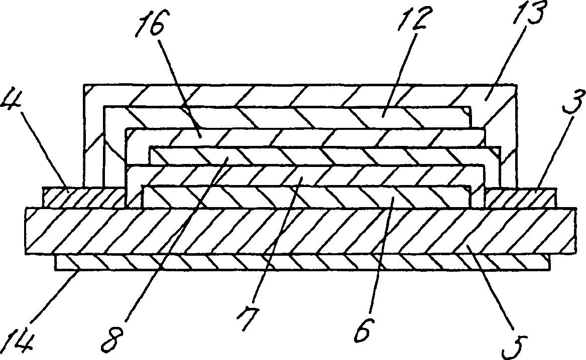
[0175] image 3 A sectional view showing a polychromatic emission dispersion type EL lamp according to a third exemplary embodiment of the present invention. because image 3Among them, the multi-color light-emitting dispersion type EL lamp has: a transparent resin film 5, a first translucent electrode layer 6 disposed on the first surface side of the transparent resin film 5, a first translucent electrode layer 6 disposed on the first translucent electrode layer 6 A luminous body layer 7, the second light-transmitting electrode layer 8 arranged on the first light-emitting body layer 7, the second light-emitting body layer 16 arranged on the second light-transmitting electrode layer 8, and the second light-emitting body layer 16 arranged on the second light-emitting body layer The back electrode layer 12 on the layer 16 is arranged to cover the insulating protective layer 13 of the above-mentioned multiple layers, the color coating layer 14 arranged on the second surface side...
PUM
 Abstract
Description
Claims
Application Information
 - R&D
- Intellectual Property
- Life Sciences
- Materials
- Tech Scout
- Unparalleled Data Quality
- Higher Quality Content
- 60% Fewer Hallucinations
Browse by: Latest US Patents, China's latest patents, Technical Efficacy Thesaurus, Application Domain, Technology Topic, Popular Technical Reports.
© 2025 PatSnap. All rights reserved.Legal|Privacy policy|Modern Slavery Act Transparency Statement|Sitemap|About US| Contact US: help@patsnap.com


