

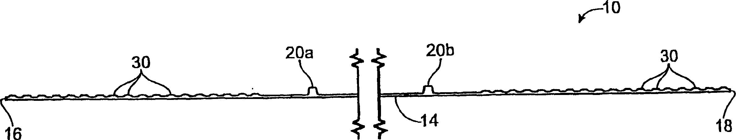
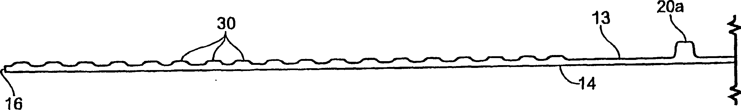
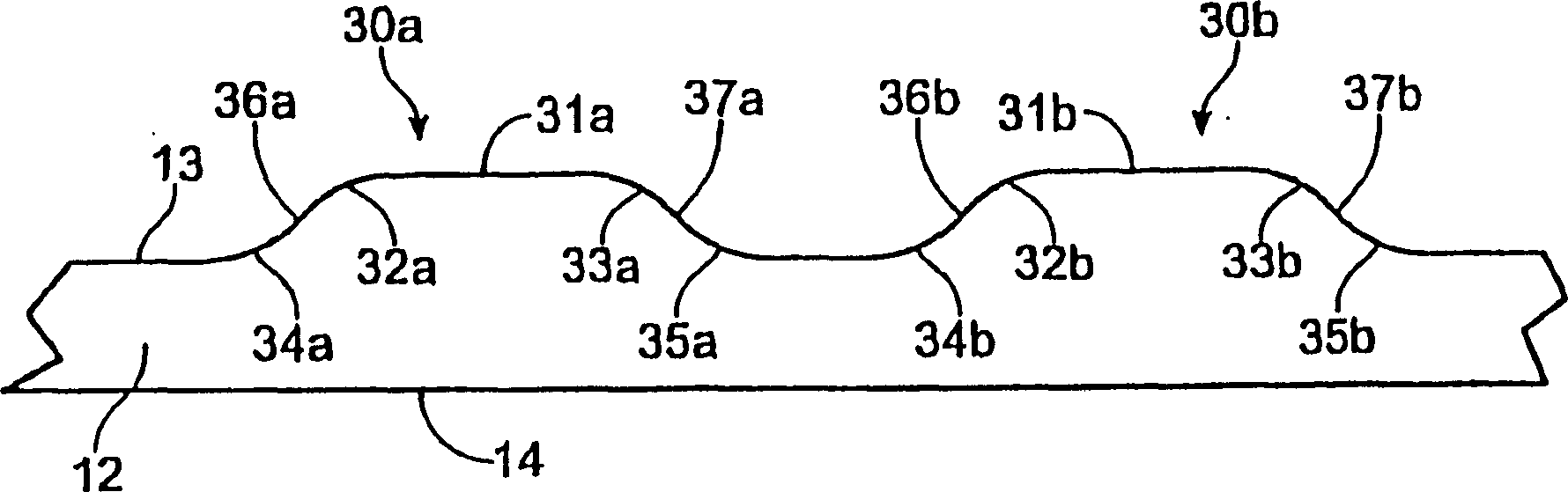
Battery separator with improved shoulders
A battery separator and flank area technology, which is applied in battery pack components, separators/films/diaphragms/spacers, circuits, etc., can solve problems such as puncture in the flank areas of the separators
- Summary
- Abstract
- Description
- Claims
- Application Information
AI Technical Summary
Problems solved by technology
Method used
Image

Examples
example 1
[0038] Fabrication of microporous polyethylene battery separators with the following features:
[0039] Partition width: 162.56mm
[0040] Back mesh thickness: 0.15mm
[0041] Main rib:
[0042] Quantity: 20
[0043] Height: 0.48mm
[0044] Width: 0.38mm
[0045] Spacing: 6.68mm
[0046] Small ribs:
[0047] Quantity: 18 (per flank)
[0048] Height: 0.10mm
[0049] Width: 0.25mm
[0050] interval:
[0051] Upper edge: 0.57mm
[0052] Center: 0.83mm
[0053] Bottom edge: 0.17mm
[0054] Others: 3.33mm (the distance between the centers of adjacent main ribs and small ribs)
example 2
[0056] The puncture resistance of the separators having the structure described in Example 1 was tested. The method used to test puncture resistance is a modified BCI test method 3.124. The modification consisted of replacing the needle dimensions determined in the original test method by needles with cross-sectional dimensions of 0.57 mm x 0.83 mm. The reason for using a needle instead is to use a needle that more closely approximates the small grid wires. The average puncture resistance for a large number of Example 1 separators was 0.75 lbs (1.65 kg).
PUM
| Property | Measurement | Unit |
|---|---|---|
| height | aaaaa | aaaaa |
| height | aaaaa | aaaaa |
Abstract
Description
Claims
Application Information