A constant pressure valve device for oil and gas field wellheads

A constant pressure valve, gas field technology, applied in valve device, valve details, control valve and other directions, can solve the problems of affecting the pressure regulating and constant pressure performance of the constant pressure valve, the consumption of human resources, and the loss of the regulating function of the constant pressure valve.

Active Publication Date: 2022-07-01
CHINA PETROLEUM & CHEM CORP +1
View PDF0 Cites 0 Cited by
  • Summary
  • Abstract
  • Description
  • Claims
  • Application Information

AI Technical Summary

Problems solved by technology

For example, with the increase of gas injection wells in the oil field, the oil casing pressure at the wellhead reaches above 40MPa, and the common constant pressure valve is welded as a whole, so the pressure bearing level is 15MPa, which is difficult to reach the equipment pressure level, and there is a risk of well control. During the process, the fluid will damage the welding joint. When the flow rate is too fast, it will cut the welding joint, resulting in leakage, which poses a certain safety hazard
The traditional constant pressure valve does not have a pressure adjustment scale. When manually adjusting, it needs to be observed by on-site personnel. It can only be confirmed after it is confirmed that it is opened under the set pressure, resulting in the consumption of human resources and low efficiency.
In addition, when the traditional constant pressure valve adjusts the pressure, it is easy to cause the internal ball to fall off and be transferred into the outlet channel, so that the constant pressure valve loses its regulating effect
Moreover, the material of the traditional constant pressure valve has not been treated with anti-H2S
These have seriously affected the pressure regulation and constant pressure performance of the constant pressure valve.

Method used


Image

  • A constant pressure valve device for oil and gas field wellheads

Examples


Embodiment Construction

[0018] The present invention will be described below with reference to the accompanying drawings.

[0019] It should be noted that the directional terms or qualifiers "upper", "lower", "inner", "outer" and the like used in the present invention are all for the referenced drawings. They are not intended to define the absolute position of the components involved, but can vary on a case-by-case basis.

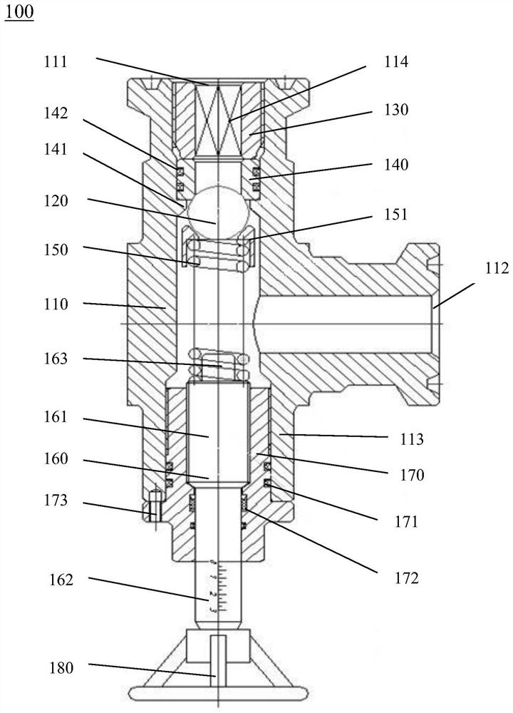
[0020] figure 1 The structure of a constant pressure valve device 100 for oil and gas field wellheads according to the present invention is shown. like figure 1 As shown, the constant pressure valve device 100 includes a valve body 110 . The valve body 110 is configured as a three-way structure, including the valve body inlet end 111 for injecting oil and gas, the valve body outlet end 112 for discharging oil and gas, and the pressure regulating end 113 for installing pressure regulating parts. The outlet end 112 of the valve body extends along the radial direction of the valv...


PUM


Abstract

The present invention provides a constant pressure valve device for oil and gas field wellheads, comprising: a valve body configured with a three-way structure, the valve body comprising an inlet end of the valve body, a valve extending radially along the valve body The outlet end of the valve body and the pressure regulating end of the valve body axially opposite to the inlet end of the valve body; a ball seat installed inside the inlet end of the valve body, and a ball ball is arranged on the ball seat; A spring arranged inside the valve body for providing the pressure value of the constant pressure valve device; a valve stem arranged at the pressure regulating end of the valve body for adjusting the elastic force of the spring; wherein, the spring One end is fixedly connected with one end of the valve stem, and the other end of the spring presses the ball on the ball seat, so that oil and gas can only enter from the inlet end of the valve body, It is discharged from the outlet end of the valve body, and the elastic force of the spring can be adjusted by rotating and adjusting the valve stem to set the pressure value of the constant pressure valve device.

Description

technical field [0001] The invention relates to the technical field of wellhead blowout prevention and leakage prevention equipment, in particular to a constant pressure valve device used for oil and gas field wellheads. Background technique [0002] In recent years, with the development of oilfields, the requirements for oilfield wellhead equipment are getting higher and higher. There is usually a constant pressure valve at the wellhead to adjust the wellhead pressure to avoid well control risks. [0003] However, there are still some problems with the existing pressure relief and constant pressure valve. For example, with the increase of gas injection wells in the oil field, the casing pressure at the wellhead reaches more than 40MPa, and the common constant pressure valve is welded as a whole, so the pressure level is 15MPa, which is difficult to reach the equipment pressure level, and there is a risk of well control. During the process, the fluid will damage the weldin...

Claims


Application Information

Patent Timeline
Patent Type & Authority Patents(China)
IPC IPC(8): F16K15/04F16K15/18F16K27/02
CPCF16K15/044F16K15/18F16K27/0209F16K27/0245
Inventor 毛谦明杨晓东李磊磊许发明赵帅领党文涛张吉德赵鑫张淑会梁宇超
Owner CHINA PETROLEUM & CHEM CORP
Why Eureka
Try Eureka