Hydraulic circuit control device of construction machinery

A technology for construction machinery and control devices, which is applied to fluid pressure actuating devices, construction, mechanical equipment, etc., and can solve problems such as intermittent feeling, inability to obtain acceleration, deceleration, and intermittent feeling in response to operation quantities. , to achieve the effect of agile reversal action

Inactive Publication Date: 2005-01-05
NIHON KENKI CO LTD
View PDF5 Cites 0 Cited by
  • Summary
  • Abstract
  • Description
  • Claims
  • Application Information

AI Technical Summary

Problems solved by technology

[0015] First of all, the first problem is that the setting value of the maximum operation speed (the maximum change speed of the operation signal) of the limit operation valve (flow control valve) does not correspond to each of the time of acceleration, deceleration and stop, and reverse lever operation. Setting, it is not necessarily possible to control the operation valve at the most appropriate maximum change speed according to the operating conditions of the construction machinery
[0016] The second problem is that the insensitive area near the neutral of the flow control valve cannot be properly processed when the reverse lever is operated, or it cannot be processed at all. When the reverse lever is operated urgently, an impact is generated near the neutral, and the actuation The device does not move, there will be a sense of intermittent
[0017] The third problem is that the maximum change speed of the operation valve is limited only by a fixed modulation pattern regardless of the operation amount of the operation lever, and the sense of acceleration and deceleration in response to the operation amount cannot be obtained.
However, since the control object caused by the operating lever is the pump volume variable mechanism, the insensitive area near the neutral of the flow control valve is not considered
For this reason, when it constitutes a hydraulic circuit control device used to control the speed of the actuator through the flow control valve, when the flow control valve is in the insensitive area near neutral, the maximum change speed of its original operating signal is limited, and during the actuation There will be a sense of discontinuity in the area where the device does not move (question 2)

Method used


Image

  • Hydraulic circuit control device of construction machinery
  • Hydraulic circuit control device of construction machinery
  • Hydraulic circuit control device of construction machinery

Examples


Embodiment Construction

[0058] Hereinafter, embodiments of the present invention will be described based on the drawings.

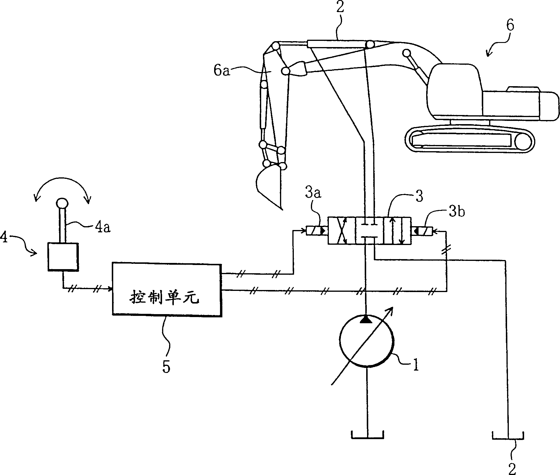
[0059] figure 1 This is an embodiment when the present invention is applied to a hydraulic circuit control device of a hydraulic forklift as a representative example of a construction machine. but, figure 1 For ease of description, only part of the hydraulic circuit control device associated with the hydraulic cylinder driving the fork arm of the hydraulic forklift is shown.

[0060] in figure 1 In the hydraulic circuit control device of this embodiment, a hydraulic pump 1, a hydraulic cylinder, etc., an actuator 2, a flow control valve 3 that controls the inflow direction and flow rate of the pressure oil discharged from the hydraulic pump 1 toward the hydraulic cylinder, and a drive flow rate The electromagnetic proportional valves 3a, 3b of the control valve 3, the operating lever device 4 having an operating lever 4a and outputting an electrical operation signal indicating t...


PUM


Abstract

Whether or not a valve command value Y-1 computed previously is in a neural region + / - alpha is judged, and, if YES, a neutral dead zone valve command value computation is performed, or, if NO, a drive region valve command value computation is performed. In the latter case, a lever command value X and the preceding valve command value Y-1 are used to judge an operation status, whether at accelerating, decelerating, halting or lever reversing, maximum set speeds at accelerating, decelerating, halting and lever reversing are respectively computed from a function, DELTA Y=fmax1 (X), or the like, a control signal for controlling a change speed of an operation signal to below its maximum change speed is computed, and a flow rate control valve (3) is controlled by the control signal. A hydraulic drive device which controls, based on the above sequences, a flow rate control valve by an electric operation signal to control the operation of an actuator, wherein the flow rate control valve can be controlled at an optimal maximum change speed in any one of the operation statuses, accelerating, decelerating, halting and lever reversing.

Description

Technical field [0001] The present invention relates to a hydraulic circuit control device of a construction machine, in which the operating system of the construction machine, particularly an operating lever device, uses a control lever device in the form of generating an electric operation signal (electric signal) in response to the operation amount of the operating lever, and is operated by The operation signal controls the flow control valve to control the action of the actuator. Background technique [0002] In recent years, construction machinery, especially machinery such as hydraulic forklifts, which are used for various tasks due to their convenience, has a tendency to attach importance to operability in order to adapt to various uses. That is, the hydraulic bucket must be a machine that can operate the work device according to the operator's will, from work that emphasizes the amount of work, such as excavation work, to operations that require subtle adjustments, such a...

Claims


Application Information

Patent Timeline
IPC IPC(8): E02F9/22F15B11/08F15B21/08
CPCE02F9/2228E02F9/2203E02F9/2296F15B21/087E02F9/20
Inventor 渡边洋大平修司藤岛一雄小仓弘羽贺正和富田祯久
Owner NIHON KENKI CO LTD
Why Eureka
Try Eureka