
Low-voltage circuit breaker composing a switching chamber and a displaceable contact bearer

A low-voltage circuit breaker and switch box technology, which is applied in the directions of circuit breaker contacts, circuit breaker components, and electrical switches, can solve the problems of increasing pole distance, large width error, and error generation, and achieves low motion resistance and favorable The effect of size design

Inactive Publication Date: 2005-02-02
SIEMENS AG
View PDF4 Cites 0 Cited by
  • Summary
  • Abstract
  • Description
  • Claims
  • Application Information

AI Technical Summary

Problems solved by technology

[0005] Despite the simplicity and practicality of the described known structure composed of a plurality of individual components, the addition of the individual tolerances results in comparatively large width tolerances, namely the sheet metal tolerances on both sides and the tolerances of the central part
Contrary to the advantage of having a suitable manufacturing method for each component, a multi-step process is required to manufacture the contact support consisting of individual components, during which errors may occur
Furthermore, when the arms are made of metal or sheet metal, in contrast to the advantages of high strength at the same time as small dimensions, additional measures may be required to keep the circuit breaker adjacent in order to enable voltage transfer from the contact rod to the support neck area. poles are insulated from each other, so they have to increase the pole distance

Method used


Image

  • Low-voltage circuit breaker composing a switching chamber and a displaceable contact bearer
  • Low-voltage circuit breaker composing a switching chamber and a displaceable contact bearer
  • Low-voltage circuit breaker composing a switching chamber and a displaceable contact bearer

Examples


Embodiment Construction

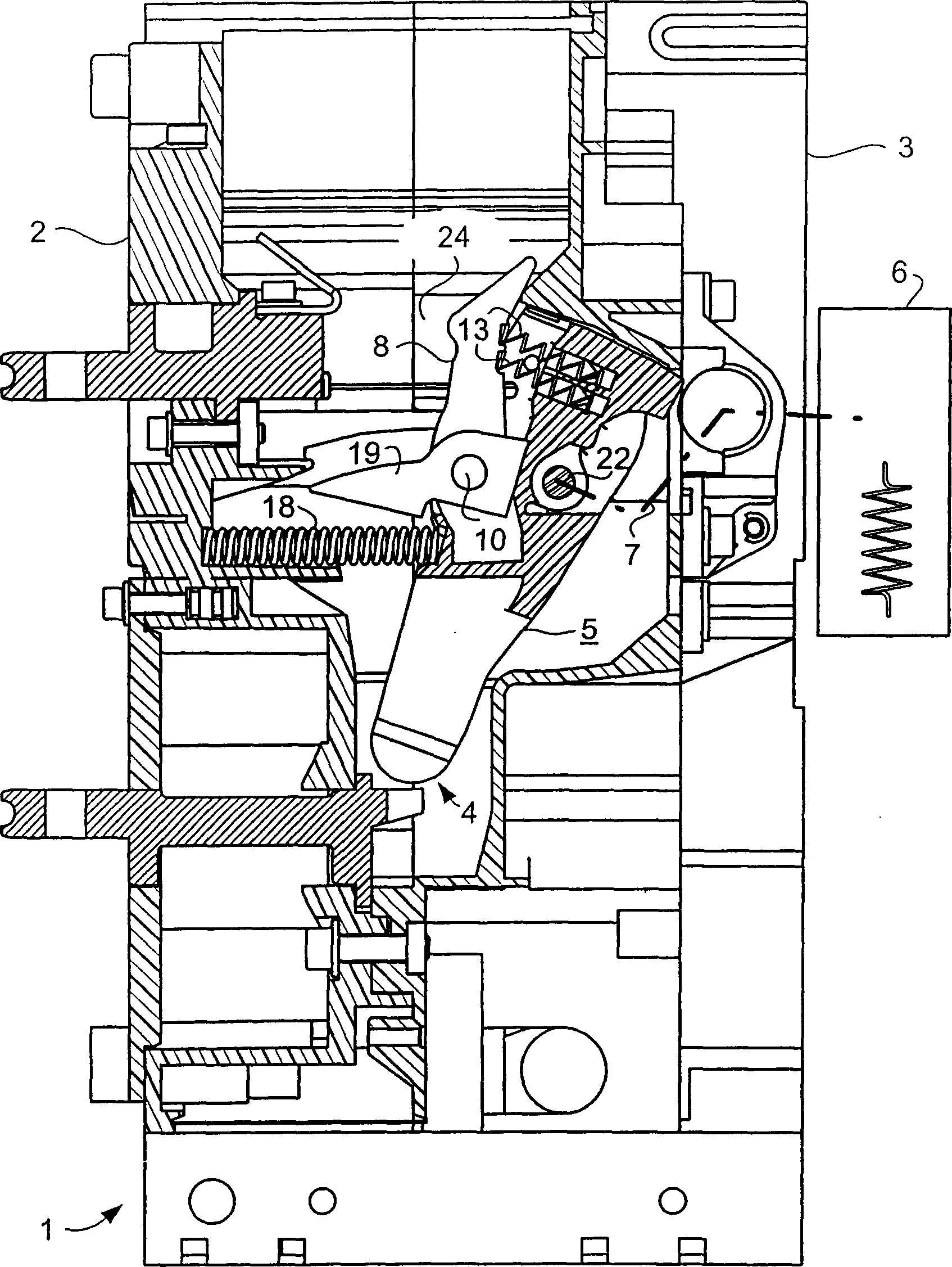
[0024] figure 1 The switch box 1 of the low-voltage circuit breaker represented in is composed of a rear wall 2 and a front part 3 . The rear wall 2 supports, in a known manner, connection curves for the connection of the circuit breaker to an external circuit. In the region of the junction between the rear wall 2 and the front part 3 there is a bearing point 4 for pivotably mounting the contact bearing 5 . The driver 6 schematically shown in the figure and the lever system 7 connecting the driver 6 and the contact support 5 are used to rotate the contact support 5 around the support point 4 in order to switch on and off the circuit breaker.

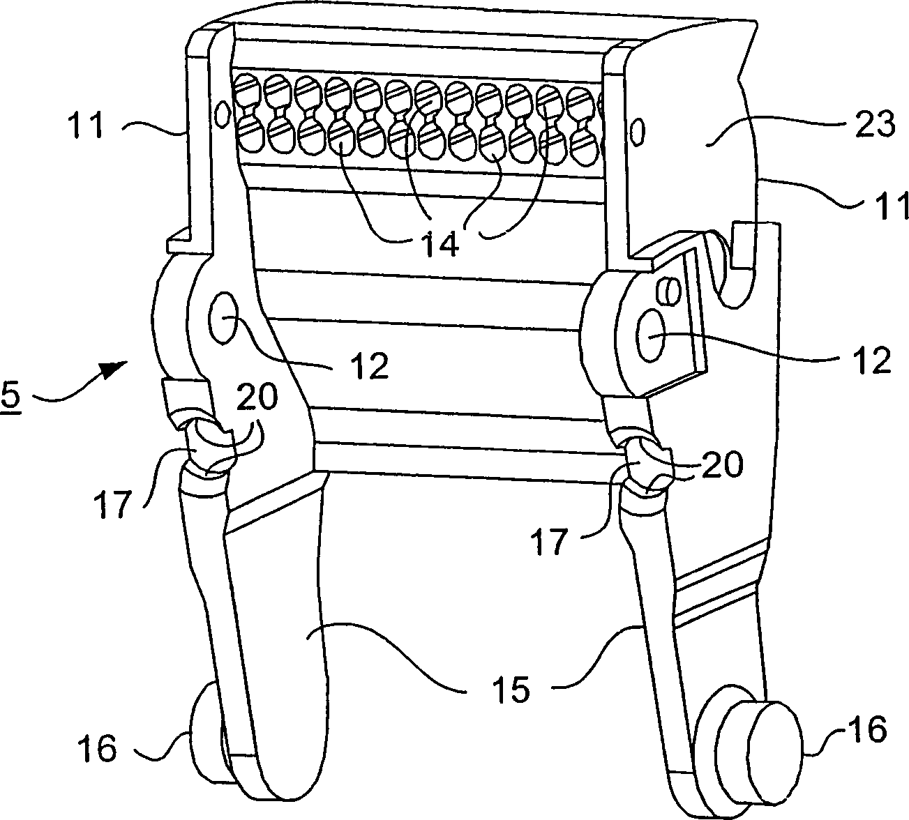
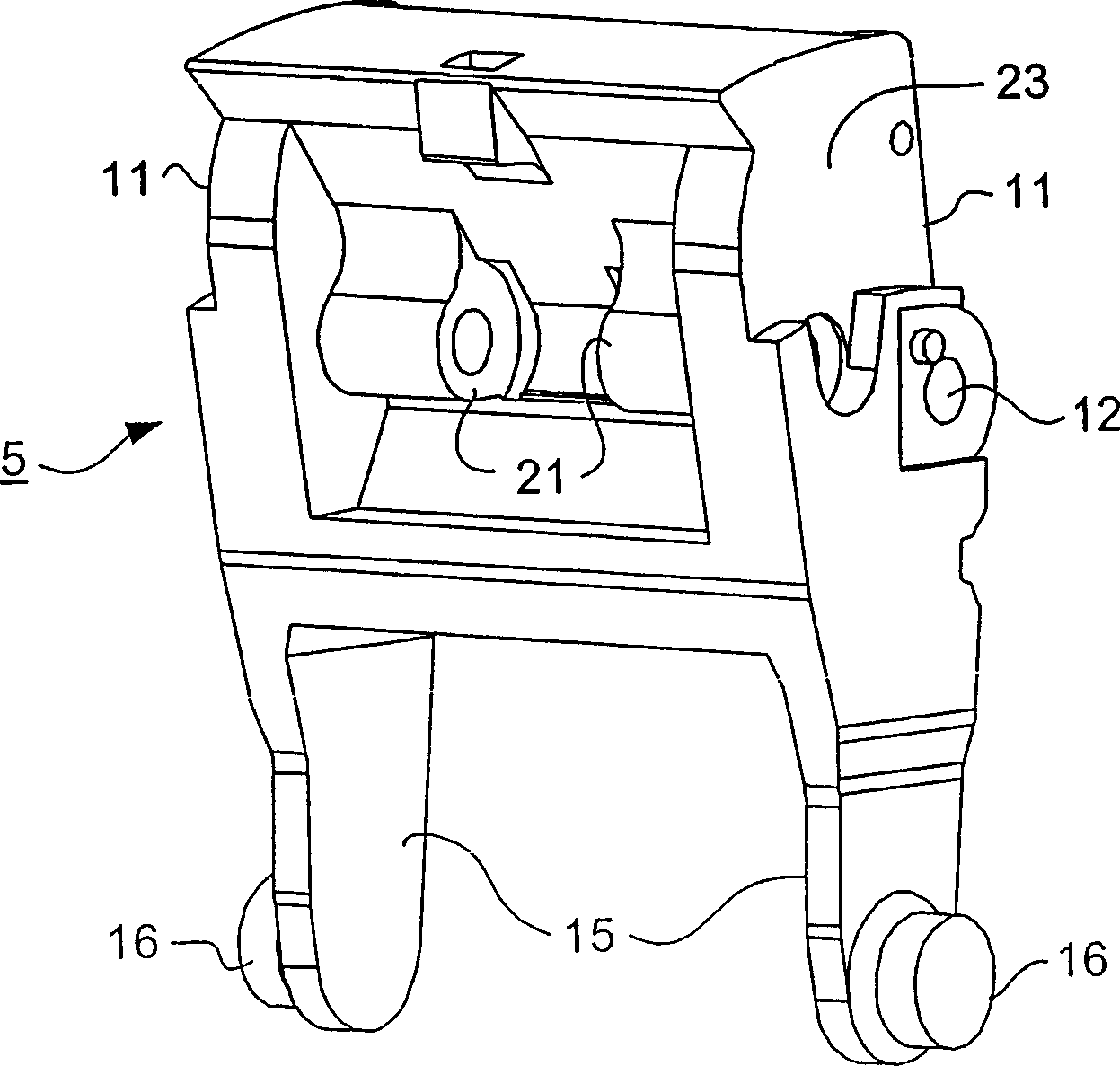
[0025] refer to below figure 2 and 3 To further illustrate the contact support, since these two figures can be compared with only the figure 1 The individual features of the contact carrier 5 can be seen more clearly.

[0026] The contact support 5 is used to place the contact rod 8 ( figure 1 ), the number of contact rods corresp...


PUM


Abstract

The invention relates to a low-voltage power circuit breaker, comprising a contact unit (5), specifically designed to accommodate contact levers (8), which has receiving bores (12) for a bearing bolt (10) that passes through the contact lever (8). Lateral bearing arms (15) with projecting lugs (16) allow a pivotal displacement of the contact unit (5) for making and breaking contact. Said bearing arms mesh with bearing points (4) of the switching chamber. A lever chain (7) is used to transmit an actuating force from a drive device (6) to the contact unit (5). Bearing means (21) for an articulated bolt (22) are provided on said contact unit to couple the lever chain (7). The contact unit (5) is supported against forces which act in a transverse direction to its pivotal axis by lateral guide surfaces (23). Receiving means (20) for a spring (18) which maintains the final position can also be fitted to the contact unit (5). Said receiving means holds the contact unit (5) under tension in its circuit-breaking final position. The contact unit (5) and its aforementioned features is produced from plastic as a single-piece multi-purpose part. The inventive contact unit (5) is particularly suitable for multi-pole low-voltage power circuit breakers, in which the neighbouring pole lies a short distance away.

Description

technical field [0001] The invention relates to a low-voltage circuit breaker comprising a switch box and a contact support rotatably mounted in the switch box for accommodating a contact rod. Background technique [0002] Hitherto, in circuit breakers for high rated currents with large-sized contact supports with several parallel contact rods, a combined structure has always been used, in which one body is only used to accommodate one contact rod, and in these The sides of the body are screwed or otherwise fitted with side walls or levers, generally designed as metal parts, which allow the pivoting of the contact bearings on the relevant support points in the switch box. [0003] Such a movable contact carrier is known from DE 3539786 A1. There the support arm is a component of the support bow, which is dimensionally fitted to the fixed body of the contact rod. In this case it is a structure consisting of several metal parts. Since the entire contact carrier is electrica...

Claims


Application Information

Patent Timeline
IPC IPC(8): H01H1/22H01H73/04
CPCH01H73/04H01H1/226H01H2001/228
Inventor 迈克尔·巴赫德特莱夫·施米特迈克尔·西布科夫英戈·蒂德塞扎伊·图尔克曼冈特·塞德勒-斯塔尔
Owner SIEMENS AG
Learn More